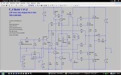
The power amplifier detailed here is an evolution of my M1 lateral FET amp that has proved so successful in daily use.
This has all been a learning adventure for me in using LTspice (yes I know I need a new signature") ) but I have been surprised and impressed with the results obtained... and so I am posting the files in the hope that any glaring errors in the design or test set up come to light. (And believe me, I've made a few really daft ones using Spice in getting this far).
) but I have been surprised and impressed with the results obtained... and so I am posting the files in the hope that any glaring errors in the design or test set up come to light. (And believe me, I've made a few really daft ones using Spice in getting this far).
This design switches from Laterals in the M1 to HEXFET's
Some quick figures,
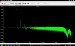
THD 0.00018% at 1Khz and 1 watt
THD 0.0020% at 1Khz and 90 watts
THD 0.0042% at 1Khz and 1 watt
THD 0.005% at 20 Khz and 90 watts
The harmonic distortion plots seem to me to be quite good.
For all you Class A fans, try increasing the bias.
I would also like to thank Bob Cordell at this point, whose recent book was the inspiration I needed to begin using LTspice. The test data and files all follow the methods outlined in the book.
This has all been a learning adventure for me in using LTspice (yes I know I need a new signature
) but I have been surprised and impressed with the results obtained... and so I am posting the files in the hope that any glaring errors in the design or test set up come to light. (And believe me, I've made a few really daft ones using Spice in getting this far).This design switches from Laterals in the M1 to HEXFET's
Some quick figures,
THD 0.00018% at 1Khz and 1 watt
THD 0.0020% at 1Khz and 90 watts
THD 0.0042% at 1Khz and 1 watt
THD 0.005% at 20 Khz and 90 watts
The harmonic distortion plots seem to me to be quite good.
For all you Class A fans, try increasing the bias.
I would also like to thank Bob Cordell at this point, whose recent book was the inspiration I needed to begin using LTspice. The test data and files all follow the methods outlined in the book.
Attachments
Last edited:
The single ended input stage does have advantages, particularly in the distortion spectra it produces compared with the LTP. The big downside is the need to arrange a suitable bias voltage, something the servo does.
The M1 amplifier from which this is a development is here. You can see how the servo bias the input stage.
http://www.diyaudio.com/forums/solid-state/119151-my-mosfet-amplifier-designed-music.html
The M1 amplifier from which this is a development is here. You can see how the servo bias the input stage.
http://www.diyaudio.com/forums/solid-state/119151-my-mosfet-amplifier-designed-music.html
The DC servo output is summed with the AC input to counter offset. I made an amp similar to that one, just playing around. It sounded quite good. Mine was the other way around, NPN input transistor with a J-fet buffer. Also I used a descrete LTP & VAS as the servo and BJT outputs. (Use of Op-Amps is cheating) The servo had a CCS for IPS tail current and a CCS for VAS bias to the low voltage -V, and a resistor to GND load, ~2 orders lower than the AC input Z.
Also I used a descrete LTP & VAS as the servo and BJT outputs. (Use of Op-Amps is cheating) The servo had a CCS for IPS tail current and a CCS for VAS bias to the low voltage -V, and a resistor to GND load, ~2 orders lower than the AC input Z.I'm sorry, but i couldent resist: http://i.imgur.com/rk7Bo.png
Lower the power about 10 watts and THD drops to 0.014%
Yes i know the Single ended IPS is not really suitable for a high power amplifier like this but i just had to try it
Lower the power about 10 watts and THD drops to 0.014%
Yes i know the Single ended IPS is not really suitable for a high power amplifier like this but i just had to try it
The DC servo output is summed with the AC input to counter offset
The servo is one area that needs more work in my design. Although it works well in practice I would like to investigate more of a "fixed" bias scheme perhaps with only a small influence from a servo that has a very limited range.
I'm sorry, but i couldent resist: http://i.imgur.com/rk7Bo.png
Lower the power about 10 watts and THD drops to 0.014%
Yes i know the Single ended IPS is not really suitable for a high power amplifier like this but i just had to try it
We have a bjt power fan
Interesting topology none the less, seem to be based on the older amp designs seem in the 70's before the LTP IPS was introduced.
And using a mosfet for the Vbe multipler is something seldom seen.
Not so, if youd like I can mention you over 30 such amps in the last couple of years produced for hi fi market, they range from midfi type price points to 3 models that youd could say are more in line with botom priced esoteric types.
Mooly this looks a lot better than your previous effort, Id do some changes with the way its compensated and part choices but this would work nicely as is. Try JFEt bjt cfp as input and temp comp the current source, it only takes one more zener diode and servo will have less work to do.. Have a look at thule audio amps for some ideas regarding this design.
Go ahead, this topology sounds pretty good in various guises and its hard to really make it sound bad. I like to use hawksford cascoded vas and Jfet input with it coupled to triple outputstage and use of combination of shunt compensation and from vas to input emiter like In Mooly s amp.
Mods, please change the thread title - it's about V-MOSFETs (HEXFETs), not the V-FETs (2sk60, 2sj18, 2sk82 and similar).
This way it's misleading...
F_V refers to the name of the amplifier.
Attachments

Mooly this looks a lot better than your previous effort, Id do some changes with the way its compensated and part choices but this would work nicely as is. Try JFEt bjt cfp as input and temp comp the current source, it only takes one more zener diode and servo will have less work to do.. Have a look at thule audio amps for some ideas regarding this design.
Thanks...
Some of the parts do look a bit unlikely such as the power device used as an input stage. Probably more suited to a common base amp configuration but it worked well in Spice here too.
And thanks for the suggestions, I'll see what I can turn up.
Not much wrong with the input choice, I like to use a small signal BJT (like mpsa18) with very high beta and lower early voltage, a little more THD but its only in 2nd harmonics and 20 khz distortion slightly better due to lower Cob. The beta helps with the offsets as well but in all the Jfet way is better to me. Design a pcb for it, its a nice project for other diyers to build, they wont be dissapointed, its not easy to get a blameless type amp to sound as good as this simple circuit does.
The servo is one area that needs more work in my design. Although it works well in practice I would like to investigate more of a "fixed" bias scheme perhaps with only a small influence from a servo that has a very limited range.
Hi
In my latest amp I used for the DC servo comparator a new device called and E-pad from Advanced Linear Devices. Partly because I wanted to get more familiar with them, and of course for the accuacy. E-pads are programable matched mosfet arrays for analog applications. They are low voltage devices and so I simply used a N-ch J-fet and a P-ch J-fet to provide +/-3V for this DC servo to operate. (drain to resistor to higher voltage, gate to GND, source is the output) I plan to use these in the future for more applications, they can be easily cascode for higher voltage apps and are pretty cool! Although they are very fragile, I have had no issues at all thus far, and the DC bias of the amplifier output is less than a few mV.
The amplifier should be bias without the DC servo to be very close to 0VDC. Temperature will cause minor drift, this where the servo comes in.Not much wrong with the input choice, I like to use a small signal BJT (like mpsa18) with very high beta and lower early voltage, a little more THD but its only in 2nd harmonics and 20 khz distortion slightly better due to lower Cob. The beta helps with the offsets as well but in all the Jfet way is better to me. Design a pcb for it, its a nice project for other diyers to build, they wont be dissapointed, its not easy to get a blameless type amp to sound as good as this simple circuit does.
Have to agree with you on the "blameless amps". The sound quality of the Lateral FET amp absolutely blows the well documented "50 watt blameless" out of the water on sonics. And I hope this design would build on the strengths of the lateral although I'm not really sure in what areas it would be apparent sonically. From a purely technical level I'm looking at better low impedance drive ability and better PSU rejection ratio hence the two HT rails. Running a Spice sim on the lateral amp and this shows massive gains in that area.
Hmmm... so at some point a breadboarded version is needed for a "proper" test
Such things as getting a feel for offset drift and so on I think can only be done that way.
The LT1166 bias spreader Bob C mentions might be worth a look too. Is there a Spice model ? I'll have to look.
- Status
- This old topic is closed. If you want to reopen this topic, contact a moderator using the "Report Post" button.
- Home
- Amplifiers
- Solid State
- F_V FET Power Amplifier With Single Ended Input Stage