TL783: Min current to maintain regulation: 15 mA. --> Not suitable in this design (see Post #1). It may work stand-alone in a preamp with low B+, but you'd get better ripple rejection by using my design.
The LR8... can only provide 10 mA which isn't enough to power much of a power amp.
That's what I get from glancing over their data sheets. I have no personal experience with the devices.
~Tom
Tom,
I've worked with both.
The TL783 from TI does have a mimimum current of 15 ma. but this is easily absorbed driving output tubes.
http://www.ti.com/lit/ds/symlink/tl783.pdf
The LR8N from Supertex doesn't have the 15ma. min current requirement. It works well in preamp applications with low plate currents.
http://www.supertex.com/pdf/datasheets/LR8.pdf
Not trying to defer from your design, it looks quite good.
Best,
Rob
The shipping charge covers the cost of shipping plus a few percent to cover Paypal fees. I have settled on $18 as a reasonable flat rate for international shipping. For most countries, it works out to cover exactly the rate USPS charges plus the paypal fees. For a few countries I lose money.
~Tom
Totally understand - and I fully appreciate there are many hidden charges for anyone doing this kind of thing. Please don't think I was taking a shot or voicing a criticism...
Thanks for taking the time to respond.
Fran
I've read through the thread, but can't find the answer to this question: Will this regulator work well in a preamp drawing only 6mA of current per channel, at 120-150V? Most of the talk here centers around amps, not preamps, so you're talking much higher voltages and currents. Will one of these per channel work well at only 120V and 6mA?
Totally understand - and I fully appreciate there are many hidden charges for anyone doing this kind of thing. Please don't think I was taking a shot or voicing a criticism...
No worries. I didn't take offense to your question. But you're not the only one asking that question, so I figured I'd explain my reasoning in public. I'm sorry if I came across as crass or on the defensive in my reply. I tend to go a little overboard on the details of an explanation at times.
But hey... If you want to buy 20 boards and be my European distributor, you're more than welcome to...
")
~Tom
I've read through the thread, but can't find the answer to this question: Will this regulator work well in a preamp drawing only 6mA of current per channel, at 120-150V? Most of the talk here centers around amps, not preamps, so you're talking much higher voltages and currents. Will one of these per channel work well at only 120V and 6mA?
I see no reason why it wouldn't work well. I have designed the regulator such that it does not require any external minimum load, so while the 6 mA is very much on the light side, I don't think it'd be an issue. I'd use 68 kOhm, 2 W for R9 and 68 ohm, 1 W for R3. See my website for more detail (I updated it yesterday). You may have to experiment a little with R9 to get exactly the range you need, but I suspect you'll be able to hit both 120 V and 150 V with R9 = 68 kOhm.
At that low current, the cascode device (Q1) will likely not even need a heat sink. You can just bolt it to the chassis (metal, I assume) and it'd be just fine. Just remember to put a thermal pad (mica washer or Silpad) between the case of Q1 and the chassis/heat sink.
But you're right. The discussion here has centered on using this regulator in a power amp application. That's mostly because that's how I'm using it and I have a little tunnel vision going. I did include the lower voltages, currents on my website to cater a bit to the line amp crowd (soon to include myself).
~Tom
Last edited:
I've read through the thread, but can't find the answer to this question: Will this regulator work well in a preamp drawing only 6mA of current per channel, at 120-150V? Most of the talk here centers around amps, not preamps, so you're talking much higher voltages and currents. Will one of these per channel work well at only 120V and 6mA?
For the light duty described, 1 little, TO92 case, LR8 per channel is (IMO) quite sufficient.
For the light duty described, 1 little, TO92 case, LR8 per channel is (IMO) quite sufficient.
As long as you don't hit the 10 mA current limiter. And as long as you can live with 50 dB of ripple attenuation. Those regulators are optimized for use in start-up circuits of switchmode supplies, hence, don't offer that great specs. I would probably choose a zener stack with an emitter/source follower over any of them.
But yes. There are many ways to skin a feline. (As a cat person I really don't like that expression... It's accurate, though.)
~Tom
Tom,
I appreciate your circuit but give the chip its due. 50 db is minimum, typical is 60 and current max is 30 ma. ,not 10, more than enough to run a line amp. At 57 cents a piece from Mouser you can use two (or more), one for each tube in your amp, now they have 60 ma. capability.
Zener's are noisy devices and far inferior regulators.
Rob
Sorry, that's 72 cents.
Attachments
Last edited:
Thanks for the answers, all!
It looks like there are lots of options at those levels. I'm currently using CCS-fed VR tubes, 0D3 and 0A3 in series per channel, and they work well (and look pretty cool, too!). It's a two-box 26 tube preamp, with the VR tubes and the 26s in one box and the LCLC power supply and filament supply in the other. Since I'm using choke input, there is a minimum current draw requirement that I'm satisfying with the VR tubes running at 22.5mA shunt on each side. If I went to a chip solution I'd either have to go to CLCLC or add a bleeder resistor to take care of the minimum draw (~18mA total).
I suppose I could move the VR tubes into the power supply box and add a chip regulator in the preamp box, but I'm not sure about the benefits of cascading regulators like that. It might help remove any noise generated by the VR tubes themselves...
The gas discharge regulator/CCS setup is just fine. Parallel each of the glow tube stacks with a .047 μF cap., to tame the "whoosh".
Thanks, Eli. Already have a 0.1uF Multicap PPMFX in parallel to each stack. I know it's a bit high in capacitance but I can detect no oscillation on my scope, and it sounds nice.
Tom,
I appreciate your circuit but give the chip its due. 50 db is minimum, typical is 60 and current max is 30 ma. ,not 10, more than enough to run a line amp.
Actually, the current listed in the LR8 datasheet is the current of the current limiter. I.e. the chip will limit the current at minimum 10 mA, maximum 30 mA. So I wouldn't plan on getting more than 10 mA out of it.
I read datasheets for a living so I tend to read the limits rather than the typical numbers - unless the typical numbers are backed up by statistical data that's published in the datasheet. Sorry. That's how I work.
72 cents. Yeah, if the performance is good enough, that's very tough to beat.
As I said earlier, many ways to skin a cat. I'm obviously rather proud of my work, hence, biased in that direction.
~Tom
Folks,
I managed to get a board built today and have updated the Calulator Spreadsheet with numbers for the thermal pad on the regulator IC. It turns out to have a thermal resistance of 36.2 K/W. Not shabby for a small plane. The actual IC case temperature is within 0.5 degree C of the value calculated in the spreadsheet.
I am also out of boards. More are on order and should be here in 10 days or so. If you want to be first in line for the next batch, please pre-order through my website.
~Tom
Last edited:
Actually, the current listed in the LR8 datasheet is the current of the current limiter. I.e. the chip will limit the current at minimum 10 mA, maximum 30 mA. So I wouldn't plan on getting more than 10 mA out of it.
I read datasheets for a living so I tend to read the limits rather than the typical numbers - unless the typical numbers are backed up by statistical data that's published in the datasheet. Sorry. That's how I work.
72 cents. Yeah, if the performance is good enough, that's very tough to beat.
As I said earlier, many ways to skin a cat. I'm obviously rather proud of my work, hence, biased in that direction.
~Tom
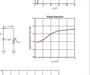
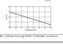
Tom,Current limit is an aspect of device dissipation.
From the data sheet:
"The LR8 has current limiting and temperature limiting. The output
current limit is typically 20mA and the minimum temperature limit
is 125°C. An output short circuit current will therefore be limited
to 20mA. When the junction temperature reaches its temperature
limit, the output current and/or output voltage will decrease to
keep the junction temperature from exceeding its temperature
limit. For SMPS start-up circuit applications, the LR8 turns off
when an external voltage greater than the output voltage of the
LR8 is applied to VOUT of the LR8. To maintain stability, a bypass
capacitor of 1.0µF or larger and a minimum DC output current of
500µA are required."
So I disagree with your 10ma. assessment, especially considering that I have used this regulator with good results.
Again, I' m not attacking your design nor have I said that it is without application.
My design philosophy is simply to use the best component for the specific application. I offered the LR8 and the higher current TL783 as alternatives for designers to consider, that is all.
Many, many times in my articles readers have asked why I didn't use an alternate component and many times it was because I wasn't aware of a simpler solution for my specific application. Taking their advice, examining their alternatives, and often employing them has made my overall designs better. Again, that doesn't mean your design is without application only that there are applications where other components are better suited.
Tomorrow you may find a better component for your design as you found better components for the original design, that's what advancing the art is all about.
It is the designer who myopically adheres to his design who loses out in the end as those with the flexibility to change surpass him or her.
Rob
Attachments
i have to rejigger my setup for measuring PSRR and Zout for high voltages, and my other Tek gets very unhappy when more than a few hundred volts are presented to its vertical amplifiers -- but here's a before and after -- the load is pretty light @20mA. 400 Volts in, 280 Volts out:
Attachments
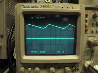
Nice!! That's what I'm seeing with 475 V in, 400 V out @ 200 mA as well.
I am curious to see what you come up with to measure the PSRR or line rejection. I tried with a transformer in series with a lab supply to inject a disturbance on the input voltage to the regulator, but the lab supply got cranky and its output voltage dropped significantly. I'm not sure why...
I suspect a source follower with a modulation signal applied to its gate would work. I'll give that a whirl at some point.
Thanks for posting your results. It's good to see that the circuit is reproducible by others.
~Tom
You can replace the STW12NK95 with any N-channel power MOS in a TO-247 package. The device will have to be able to survive the in-rush current (check the SOA curve in the datasheet) and be able to handle the input voltage applied. I used the STW12NK95 because it meets my requirements and is readily available at Digikey (my preferred disti).
If you do use devices other than the STW12NK95, please populate D4 (on the bottom of the board). The STW12NK95 has this diode built in. Other devices likely do not...
~Tom
If you do use devices other than the STW12NK95, please populate D4 (on the bottom of the board). The STW12NK95 has this diode built in. Other devices likely do not...
~Tom
Nice!! That's what I'm seeing with 475 V in, 400 V out @ 200 mA as well.
I am curious to see what you come up with to measure the PSRR or line rejection. I tried with a transformer in series with a lab supply to inject a disturbance on the input voltage to the regulator, but the lab supply got cranky and its output voltage dropped significantly. I'm not sure why...
I suspect a source follower with a modulation signal applied to its gate would work. I'll give that a whirl at some point.
Thanks for posting your results. It's good to see that the circuit is reproducible by others.
~Tom
The problem you get with transformer based current injectors is that they get saturated pretty quickly (unless it's a really, really expensive transformer) -- you're running the AC + DC current through it. The Dieckmann Current Injector scaled for HV is probably a good bet. Per Audio Precision you should check the transformer linearity and distortion at higher and higher currents.
Had you seen Jan's article on the "T-Regulator" from Elektor March 2009 -- he waxed poetic on the merits of the LT3080 as a replacement for the MC1466L. You can still find the MC1466L datasheet and apnotes on the web although On-Semi (nee Motorola) discontinued the part over 20 years ago.
- Home
- Vendor's Bazaar
- 21st Century Maida Regulator