Start reading here, its already been covered
http://www.diyaudio.com/forums/multi-way/156988-gedlee-summa-vs-lambda-unity-horn-3.html#post2025034
http://www.diyaudio.com/forums/multi-way/156988-gedlee-summa-vs-lambda-unity-horn-3.html#post2025034
Hi guys
I have to apologize for the response curve on the data sheet for the sh-50, it is an ancient one taken indoors at the shop with a woofer we don’t use anymore.
There is a new website in the works for a long time, apparently this process is taking much longer than the sales pitch.
have three new recordings waiting to be posted with the others but the web folks who made I went under. This is a problem since there are a number of new products which have no links or info on the existing web site and whatever the new ways are it isn’t comparable with the old way. I am glad I don’t know enough about that to be involved but it will be nice when it’s done, I liked the parts I have seen.
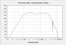
Anyway, page 5 of the white paper has a more recent SH-50 measurement from a 24KHz bandwidth impulse response measurement taken independently, with EASRA.
http://www.danleysoundlabs.com/pdf/danley_tapped.pdf
Fwiw, the horn loading and effect of the low pass filters ends around 100Hz on an SH-50 (hard to separate it into the separate bits), the lowest part is the radiation from the ports which are short passages that extend to the rear and delay the driver’s rear signal which combined with the compliance form a stubby lumped tapped horn / vented box style acoustic phase.
What is fun to demonstrate to hifi people with these is In spite of the “holes” in the horn, you can walk up and literally put your head into the horn mouth and you never hear anything other than the source floating somewhere in front of you, no trace of low, mid and high drivers, they really do combine into one new source.
There was a guy who compared them to some hifi horns too;
RE: Say what Tom? - endust4237 - Propeller Head Plaza
Best,
Tom
I have to apologize for the response curve on the data sheet for the sh-50, it is an ancient one taken indoors at the shop with a woofer we don’t use anymore.
There is a new website in the works for a long time, apparently this process is taking much longer than the sales pitch.
have three new recordings waiting to be posted with the others but the web folks who made I went under. This is a problem since there are a number of new products which have no links or info on the existing web site and whatever the new ways are it isn’t comparable with the old way. I am glad I don’t know enough about that to be involved but it will be nice when it’s done, I liked the parts I have seen.
Anyway, page 5 of the white paper has a more recent SH-50 measurement from a 24KHz bandwidth impulse response measurement taken independently, with EASRA.
http://www.danleysoundlabs.com/pdf/danley_tapped.pdf
Fwiw, the horn loading and effect of the low pass filters ends around 100Hz on an SH-50 (hard to separate it into the separate bits), the lowest part is the radiation from the ports which are short passages that extend to the rear and delay the driver’s rear signal which combined with the compliance form a stubby lumped tapped horn / vented box style acoustic phase.
What is fun to demonstrate to hifi people with these is In spite of the “holes” in the horn, you can walk up and literally put your head into the horn mouth and you never hear anything other than the source floating somewhere in front of you, no trace of low, mid and high drivers, they really do combine into one new source.
There was a guy who compared them to some hifi horns too;
RE: Say what Tom? - endust4237 - Propeller Head Plaza
Best,
Tom
Quick note regarding the group buy - drivers arrived in the US. Those who have paid - please PM address details for postage.
----
Some Synergy horns also show a falling response where horn loading is lost, with the high sensitivity gained from horn loading not going all the way down.
For home use, the bass situation is quite different. You have a much smaller room and a Shroeder frequency around 200 Hz. If one could have the ultimate I would say it's this. Get a constant beamwidth down to the SF and run horn loaded down to that point, then monopoles below. It costs a LOT more to put woofers in and go for a 3 way design and I don't see a huge benefit. You'd want at least 4 good bass drivers, that isn't cheap. A 2 way Synergy can be really cheap for what it is.
A really nice driver to do bass below a Synergy is AE TD18H. I've spent some time with Roger's while I'm getting around to painting his boxes .... think it might take me a couple of years!
Really interesting to listen to drivers sans xo. It's obvious this one has a lot of top end extension. Even with crossover filters in place you can hear the extra top end compared to say my Eminence Magnum woofers.
It costs a LOT more to put woofers in and go for a 3 way design and I don't see a huge benefit. You'd want at least 4 good bass drivers, that isn't cheap.
I agree the benefits of a full 3-way Synergy might not be worth it for some listening rooms. The points about the SF are well taken and should be considered while making the decision. You really can't go wrong, but you can go a little over board.
I also agree that the overall cost of the 3-way is more, but it doesn't need to be much more expensive. I've found the cheaper woofers actually work much better than the expensive ones in a 3-way Synergy. One of the better ones that I've used with good results is the Eminence Alpha-10A. It has just enough motor strength to horn load up to where the mids fall off. It also has the right T/S parameters for the bass reflex to peak with the small amount of air volume inside the Synergy box. The only place it is necessary to spend any real money is on the compression driver, which a BMS 4550 only runs $147 a piece. We all know the mids are pretty cheap sealed back drivers. There is no need to spend a lot of money on the woofers. Just buy what models well and throw out any preconceived notions you had about horn loading. We don't need TAD compression drivers, Accuton mids, and Eton woofers to make an outstanding sounding Synergy horn. I've been a long time hard core horn guy. It took me some time to come around on the idea of using all these inexpensive drivers, but the results speak for themselves.
Why not? If its phase coherent and the transient response behavior matches well, what's the problem?
Maybe what I implied was too harsh. I mean that it would seem more optimal to stick with the 2way Synergy for home use as you really aren't getting "horn loading" throughout the bandwidth of the woofer. I guess in this regard, it is not different than an Altec A7.
Other than better drivers, a better horn, and much better phase...it's not much different at all.
Yeah, but that's all pretty minor stuff.

-Jim
Other than better drivers, a better horn, and much better phase...it's not much different at all.
I was referring to the woofer in the 3way Synergy and how is acts like the A7 woofer section.
John (Patrick Bateman),
Clean out your inbox dude!
Interesting stuff!
Any idea why the phase response in Akabak is rotating? For instance, in hornresp the phase response seems to be what I'd expect it to be (fairly flat) but in Akabak it's rotating constantly.
The group delay curve looks correct, so I'm guessing that I'm simulating the phase wrong somehow.
You're not simulating it correctly. I had this problem too until I figured it out.
First, plot the vector response of the phase. In this case it's called "Amplitude (Phase)" in the drop-down. Once it plots the new graph, go to the top menu and select "Calc" --> "minimum phase". The node to look at is the horn mouth. This will give you the real unwrapped phase of the system.
First, plot the vector response of the phase. In this case it's called "Amplitude (Phase)" in the drop-down. Once it plots the new graph, go to the top menu and select "Calc" --> "minimum phase". The node to look at is the horn mouth. This will give you the real unwrapped phase of the system.
Greets!
To get 'in the ballpark', find one that either is a closed back unit that resonates at ~SQRT(200*1400) = ~529 Hz, or if open back, then ~529 = 2*Fs/Qes. How you get there doesn't matter if you're not trying to get max efficiency out of it with 'X' diameter x 'Y' long vents. IIRC, TD's prototype driver's published specs were ~2*250 Hz/0.99 = 505 Hz, so I wouldn't get too hung up on the apparent need for a low Qt just because it's a horn app.
GM
After studying this problem for nearly a decade, I believe the formula above fails to take into account a few variables which affect the midrange response of a Unity horn.
Basically, there are things we can do to extend the response of the midranges, and there are things we do which limit the response of the midranges.
Worst of all, I do not believe these factors are accounted for in the hornresp and Akabak simulations.
First, let's look at the predicted and measured response of the midranges in a Unity horn. I believe Paul Spencer has done the best investigation of this:
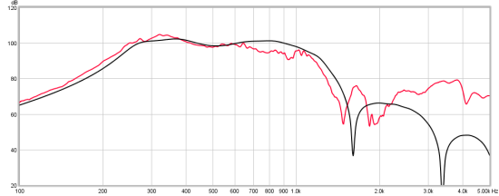
In Paul's measurement, we see the following:
- At 900hz, the measured SPL is over 5dB lower than the simulated SPL
- At 1500hz, the measured SPL is over 10dB lower than the simulated SPL
- At 3000hz, the measured SPL is over 10dB higher than the simulated SPL
These are not small differences. The scale of the graph masks the fact that the midranges have a broad depression that begins at 650hz.
So why is there so much more output at 3khz? And so much less at 1500hz?
An externally hosted image should be here but it was not working when we last tested it.
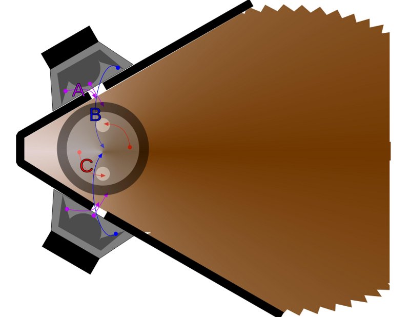
The problem that's really vexed me is how to get more output at 1500hz. And I think that I've figured out some things which hornresp and Akabak don't account for. It's the pathlength differences from the edge of the woofer cone, and a series of nulls which occur due to the distances between the four midranges.
In the picture above, I have illustrated the problem.
We have a series of nulls which aren't accounted for in the model. The nulls occur at the following locations:
First, we have a null which occurs due to the pathlength difference between the edge of the cone that's furthest from the midrange holes. In the picture, that's labeled "A" and "C" For instance, with an 11cm woofer, there's a pathlength difference which can be as long as approximately 9cm. (It's a bit less than 11cm because we're measuring from the center of the midrange hole.)
The cancellation from the edge of the cone occurs at one-half wavelength. In other words, if you draw a point from the furthest edge of the midrange cone to the midrange hole, there will be a null which occurs at one half wavelength because the sound radiating from that point is out-of-phase by one half wavelength. In the example above, with a distance of 9cm, we will get a null at 1888hz. (34000cm per second / 9cm / 2)
There's a more nefarious problem which Akabak and Hornresp do not account for. That problem is that the gap between the midranges creates a null, due to the distance between them. The reason that we do not see this in the sims is that the simulators assume that all four drivers are "on top of" each other.
Even worse, the null changes with angle!
The null is illustrated by the blue line "B" in the illustration above.
For instance, with a wall angle of sixty degrees, the midranges in the picture above are seperated by 15cm. A null will appear at a frequency of one half wavelength. In the example above, that null is at 1133hz.
Even worse, we get a series of nulls at various angles. For instance, at the center of the horn there will be a null at 2266hz, because the sound from the top midrange is 180 degrees out of phase with the sound from the center midrange. This is offset by the fact that it's IN PHASE with the opposite midrange.
If reading all of that just made your head explode, I apologize
There is a really simple and elegant solution to this though. First, use a narrower wall angle. Even reducing the coverage angle by ten degrees will move the nulls up in frequency by hundreds of hertz.
Second, I'd really think twice before using a woofer that's larger than 12cm. I've seen some people trying to get away with 15cm woofers, and that's really hard to do successfully due to the distance from the edge of the cone to the midrange holes.
Third, I think that focusing on the mass rolloff causes us to discount some drivers which don't "look good on paper." For instance, I've had good results with 5cm and 8cm drivers which appeared to be lousy candidates. I attribute this to the smaller piston size, which drives the geometry nulls much higher in frequency.
Fourth, the use of a frustum instead of a hole for the midranges serves to equalize the pathlengths. This affect is not insignificant; it can reduce the distance from the edge of the cone by as much as a centimeter or two. (Because the shortest distance between two points is a straight line, and when you use a hole instead of a frustum, the sound from the edge of the cone has to make a 90 degree bend as it exits the coupling chamber.)
In summary: If you want to fill in the range from 900hz to 3000hz in a Unity horn, use a frustum for your midrange holes, reduce the wall angle, and consider using a woofer with a smaller cone. These changes are not accounted for by Akabak or Hornresp, but make a measurable difference.
In summary: If you want to fill in the range from 900hz to 3000hz in a Unity horn, use a frustum for your midrange holes, reduce the wall angle, and consider using a woofer with a smaller cone. These changes are not accounted for by Akabak or Hornresp, but make a measurable difference.
Hmm. I've been thinking that mounting the mids on the corner of the horn, rather than on the flat sides, should make matters more predicable. Mounted this way, the single entry hole per driver could be located near the driver center. This should equalize the path lengths to the driver edges.
Mulling over your post, I still think intuitively that the corner mount would be more predictable (or more easily modeled), but it's not clear that it would be "better". That is to say, the peaks and nulls might be more predictable, but perhaps more pronounced too (or less distributed, to put it another way). The one factor you mention that wouldn't be affected is the cancellation of adjacent vs. opposite entry holes.
Sheldon
Member
Joined 2009
Paid Member
This has go to be the most fascinating speaker design I've ever seen. If you boyz come up with something suitable for my use I may just have to ride on your coat tails.
If I can ask - how complex is the cross-over design for this thing. I've seen some very scary pictures. I'd rather go with tri-amp and line level passive cross-overs. But I get the sense this speaker isn't like any other and the cross-over requires a different approach. ?
If I can ask - how complex is the cross-over design for this thing. I've seen some very scary pictures. I'd rather go with tri-amp and line level passive cross-overs. But I get the sense this speaker isn't like any other and the cross-over requires a different approach. ?
Last edited:
For anyone wanting to try to make a Unity/Synergy, I've worked up a spreadsheet to help with the design, the inputs to HornResponse, and most importantly, for figuring out the angles and dimensions of the odd pieces that need to be cut from wood.
You can get it via a post here -
DIY Synergy/Unity spreadsheet
hope that encourages anyone needing a nudge to try working with these.
My first attempt is still being assembled (glue should be dry enough for sanding tonight), will update how it works out.
You can get it via a post here -
DIY Synergy/Unity spreadsheet
hope that encourages anyone needing a nudge to try working with these.
My first attempt is still being assembled (glue should be dry enough for sanding tonight), will update how it works out.
Thanks Paul. I still have a way to go to get to the level yours are at!
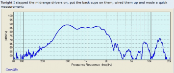
I put the midrange drivers on tonight and made a measurement (shown along with pictures on my thread at AVS forum yet ANOTHER DIY Unity, and a spreadsheet for figuring the wood cuts - AVS Forum
The cheap little 2" drivers really do all right. Not the most sensitive things in the world, but should be able to easily keep up with the non-horn type woofers I'll be matching them with. I thin I'll try to introduce some 6" woofer drivers into the horns.... just to see if I can make a full-range coaxial. These are a real fun project, your S1 and S2 builds have inspired a lot of builders to try these.
Bill,I thin I'll try to introduce some 6" woofer drivers into the horns.... just to see if I can make a full-range coaxial. These are a real fun project, your S1 and S2 builds have inspired a lot of builders to try these.
Response looks good 400 -1600 Hz, a very important two octaves, leaving a wide range of driver options above and below.
Curious why you did not simply use 6" drivers, rather than now considering adding them in addition to the 2" drivers?
I'd be very interested to see horizontal and vertical response at whatever increments you would care to do.
Art
Attachments
- Home
- Loudspeakers
- Multi-Way
- Suitable midrange cone, for bandpass mid in Unity horn.