Thank you sir. D1, D2 and D3 are in. LM318 is in.
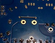
There is a HUGE difference in placing a drop of solder on a pad with ChipQuick flux and without. With it, the solder spreads evenly on the pad. Then heating the side of the pad away from the component center and sliding the SMD on to the heated pad makes the solder climb up the cap of the component for a neat solder joint.
Without the ChipQuick, the solder forms a ball on the pad and does not stick as well. It would require more heat and it seems there is more chance of a solder bridge under the component. I'm so glad I took your advice and bought it.
Thank you sir.
...
I'm so glad I took your advice and bought it.
You're welcome, Joe
")
Yes, that flux is great and makes SMD soldering way more easy.
I have populated R2, R5, R8, R6, R9, R37, R39 and R43. Placed the jumper at J1. I believe I could surgically remove hemorrhoids from a gnat's rump, should the need arise.
Did you mount the jumper on the bottom?
What's the story on C21 ?
It's optional.
Don't use it if you have a BG for C9.
Attachments
No. but I will comment on the fastons............... I am assuming such a toggle would be done with the power off, but maybe Andrew and/or others can shed some light here.
Does anyone have comments/experience with this type of arrangement. Switching between caps is so easy and immediate with the fastons it would seem to be a simple option.
Have you investigated the way the parasitics change with all the swaps?
All these component type swaps !
How has the Howland current pump set up investigation gone?
Is it always best to be negative, or it it always best to be positive?
Is it best to be very near zero and to swap repeatedly from +ve to -ve and back, as operating conditions change?
I believe that there is a strong possibility that there is a performance difference when the Howland is set up differently.
How many of you have even checked whether the current pump is set to negative or to positive or that the two channels are even similar?
Andrew, your last two posts are as usual on point. When you mention the parasitics are you talking about using one's ears or is a scope of some kind required? The fastons are of course a temporary method for testing, as I'm sure you understand.
Are you suggesting the entire topology needs to self-adjust after each swap - requiring longer intervals between changes.
"How many of you have even checked whether the current pump is set to negative or to positive or that the two channels are even similar?"
A more detailed explanation of both the impact and resolution here would be helpful and appreciated.
Last edited:
parasitics = the stray capacitances and stray inductances resulting from the closeness of conducting components.
Nothing to do with one's ears nor one's oscilloscope.
Howland and some parts of it's operation were discussed way back in the earlier Threads.
I raised that specific question and to my knowledge no one has posted a reply explaining what the difference does to the Howland Current Pump, nor confirming that anyone else has even measured whether their pump is set +ve or -ve.
http://www.diyaudio.com/forums/group-buys/160768-myref_c-ultimate-bom-16.html#post2200751
Last edited:
Howland and some parts of it's operation were discussed way back in the earlier Threads.
I raised that specific question and to my knowledge no one has posted a reply explaining what the difference does to the Howland Current Pump, nor confirming that anyone else has even measured whether their pump is set +ve or -ve.
Hi Andrew,
if there is a method to measure it with a multimeter I will be happy to check.
Can you repost/link such method?
Thanks in advance
It's almost two years ago, but I will try to explain.
The Howland Current Pump has, at it's core, a Wheatstone Bridge.
The output of a Wheatstone Bridge is critically dependent on ratios of resistors.
The resistances consist of the values of the resistors and the values of the resistances of the connections that form the bridge. Yes, the Wheatstone is so sensitive, that ignoring the resistance of the connections ruins the quality of any results one thinks one is getting.
I could set up the 0.1% resistors in a bridge format and apply the driving voltage top to bottom and read off the output from side to side. That bridge format could physically be set up as a crocodile clipped together assembly, or a soldered assembly with short lead outs from each resistor, or soldered with long lead outs from each resistor. Each different physical assembly will give a different "output" even when using the identical resistors in the identical positions in the bridge. These different "outputs" are due to the different resistances in the connections.
For those reasons, I looked very carefully at the PCB and identified the traces that formed the bridge. I also identified the few "other components" that were attached to the bridge.
I found the nodes where the 3886 measures the Wheatstone Bridge output.
I found the nodes where the AC (the music signal) drove the bridge.
I determined a method of attachment of temporary leads from a DC power supply and temporary lead to a DMM set to 199.9mVdc that would not affect the accuracy of the "output" readings from the bridge.
I checked the bridge output using my actual PCB and my actual precision resistors. Sure enough, the output was not Zero mVdc. The output could be negative, or on the second PCB the output was negative. I could change the "output" value by adding a low value resistor to the 47k or to the 22k. Yes, I could easily read changes in bridge output by changing the 47k by just 0.01%.
I had arranged my resistors such that I could alter values (micro trimming) to give +ve output, or -ve output, or high output, or low output.
The "output" is what the Howland Current Pump uses to determine the current that passes through the 3886.
It was at this point that I realised that I had a problem.
I could set up the bridge to any accuracy I wanted by making small adjustments on the PCB.
I guessed that a +ve output that was low but not too low may be good for the amplifier's final sound, but that was just me guessing.
What I didn't know was what effect those micro adjustments would have on the sound from the amplifier.
So I asked the question.
I do not have the answers.
So yes, a multimeter is all the instrumentation that is required.
Last edited:
 Thanks
The chip amp has the highest range of temperature.
Does that also mean it is the most temperature sensitive?
The manufacturer confirms it is temperature sensitive.
I have wondered what effect extreme cooling would have on the 3886 in this circuit. Something like a water cooling system from a overclocked PC.
That was not an answer. It was a couple of statements and a question.
That's what I meant. Thanks for your comments and the question = feedback
- Status
- This old topic is closed. If you want to reopen this topic, contact a moderator using the "Report Post" button.
- Home
- Amplifiers
- Chip Amps
- My_Ref Fremen Edition - Beta build/Fine tuning