Such "designs" work very well in simulators (perfectly matched components, etc...) but never work properly on the bench, or at least can't be reproduced with any degree of certainty
the servo has to be designed to measure/control the undefined current, quite possible, several have proposed, some built solutions
but yes the "eye candy" version won't work as expected with real components
I recall considering trying to use both collectors of both diff amps when modifying an existing fully-complementary design for a client and deciding it would take too much time to figure out a solution to the standing current stabilization problem. I also didn't want to make too drastic of changes as I was wishing not to offend the designers. But I did add the "beta enhancement" stages and made some device changes in the output stage.
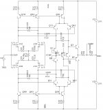
There are about 300 subwoofers with five additional amplifier channels and elaborate selectable EQ rotting in a warehouse in Carson. Despite it being not terribly apropos to this discussion, for the sake of showing something that no one cares about anymore, I attach a schematic fragment for the center channel amp.
One thing it did do was start and stop quietly, without a muting relay. Sounded good to my ears, but nothing to write home about.
Attachments
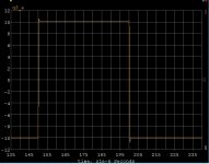
This does work (I built one) the current mirrors can be trimmed for zero offset and “infinite” gain but you need to search with the two trims. The 20K resistors “soak” up the offsets for finding common mode equilibrium but do not affect the differential gain. This differential Vas has cancellation by symmetry of the currents from Ccb and other errors. Simulated with 2N4401/4403, 2SK170/SJ74 I got 110dB Aol and ppm THD you could fiddle around and make the Aol lower and have lower open-loop BW if that’s your thing. Yes the slew (Vas) current is limited here, but you can increase the Vas current if need be without compromising input performance, easy to get 100-200 V/us. Has a clean transient too. This is not a finished circuit, there might be clamps needed in places so nodes don’t misbehave, etc.
I built one using a National power op-amp as an output and drove 100 Ohms easily (I remember posting the trimmed open-loop transfer function).
EDIT - You need to save the schematic locally so the lines don't disappear.
I built one using a National power op-amp as an output and drove 100 Ohms easily (I remember posting the trimmed open-loop transfer function).
EDIT - You need to save the schematic locally so the lines don't disappear.
Attachments
Last edited:
Such "designs"
This is not a design, but a hint. I have already stated this.
I think that PMA's 'hint' circuit is very interesting and with some judicious use of emitter resistors, can be both quiet (enough) and stable.
However, it does depart from my primary goal which is to make a design that is as simple a thru-path as possible, emphasizing the most linear open loop transfer function, and minimizing the amount of negative feedback used. This 'may' be a little too constricting when it comes to overall subjective performance, but it is my path and it has worked over the years. I hope to continue on this topic, sooner rather than later.
However, it does depart from my primary goal which is to make a design that is as simple a thru-path as possible, emphasizing the most linear open loop transfer function, and minimizing the amount of negative feedback used. This 'may' be a little too constricting when it comes to overall subjective performance, but it is my path and it has worked over the years. I hope to continue on this topic, sooner rather than later.
However, it does depart from my primary goal which is to make a design that is as simple a thru-path as possible, emphasizing the most linear open loop transfer function, and minimizing the amount of negative feedback used.
Tubes.
Be that as it may, you can still accomplish voltage amplification with better open loop linearity. If the result (high OL linearity with no global feedback) is what you care about, the supposed limitations are irrelevant- you don't need trick topologies to get performance.
I think with small emitter resistors (and a trimming network for offset) at every transistor (output stage and mirrors) such a "design" will work quite well...
No, it won't, other than by accident, and only if you keep a particular implementation at a well controlled (TBD) temperature. Try it for yourself, but be warned for the waste of time and money.
As I already said, tons of messages were posted (here, elsewhere, and over the years) about this unfortunate topology. I am surprised to find that some seasoned designers are not aware of its pitfalls.
Indeed. The problem is that tying a drain to a collector is simply, on the face of it, by itself a high impedance and poorly determined as an open-circuit. And connecting it to a base-emitter junction where the operating point is set by the device's beta, ambient- and self-heating- temperature-dependent, and collector-base voltage dependent, is simply asking for trouble. And most simulators will emphatically NOT tell you what is going on dynamically.
When overall feedback is applied the circuit may well stabilize with an appropriate output voltage, but this can obtain over a huge range of bias currents, and once again your simulator will LIE unless it is an extraordinarily sophisticated one, in which case it should do a very thorough job of talking you out of the enterprise!
Which, of course, makes it a challenge to determine how something approximating it could be made to work --- and Scott has provided such above, and there are surely other ways. But parts necessarily proliferate, and the minimalists are driven from Paradise. I don't think it's a mountain worth climbing, but then I'm not 23 anymore either.
Waly, bcarso, could you post some of your real designs, supported with measurements?
I just did. See post 22062. However, that's a power amp that has been only mildly modified to enhance the performance, and an example of NOT trying, with a fully complementary input structure, to do something along the lines you have proposed. As I say, I wouldn't even attempt the latter, as it is intrinsically problematic --- even though it does intrigue, as to how it could be made to work.
However, it does depart from my primary goal which is to make a design that is as simple a thru-path as possible, emphasizing the most linear open loop transfer function, and minimizing the amount of negative feedback used.Tubes.
No.
Piece of wire!
John, please continue.
I already discovered two interesting theories by you in this thread that I never thought of before, namely "minimizing the number of p-n junctions that the signal has to go thru" and "FM distortion" and am looking forward to hear some more.
Best,
Personally, this is how I see audio design:
Tubes are the most linear, but are restricted to current, polarity, self noise, etc.
I chose, almost 50 years ago, to concentrate on solid state, to make it as good, or BETTER than the best that tube design could provide. Moreover, Mark Levinson heard my design in action in 1968, and hired me 5 years later because of his opinion of my accomplishment, even at that time.
44 years ago, I tried to make a power amp that would do this, but I failed to beat the BEST triode amp design that was then available, at the time. I was close, but I knew that more effort was necessary. This is when I turned to trying the ideas put forth by Matti Otala in his 1970 IEEE paper. They worked, and I have never seriously looked back.
My forte is circuit topology. I have independently developed a number of circuit topologies that usually work better than contemporary approaches. Just look at PMA's spice results for further understanding. This requires thinking, (upside down) as well as normally, like most tube circuits are constructed. Many of my best designs look like a 'flower' or a 'Two Grey Hill' Indian rug design, and have been so for more than 40 years.
All else being equal, cost, sophistication, etc. Tubes can be made at least as good as anything I can make with solid state, but I can get close, and often offer a better approach by offering more peak current, for example, from a power amp, or lower noise, without the use of either input or output transformers, and even eliminating any coupling caps from moving coil input, all the way to power amp output. That's the progress that has been made over the last 40 years.
Last edited:
<snip>
Many of my best designs look like a 'flower' or a 'Two Grey Hill' Indian rug design, <snip>
Oh yes, there is something about the beauty of circuit drawn and imagined in engineers head and final sonic result. I've always believed in that.
Some airplane designer once said : "Only beautiful aircraft can fly".
Here's two channel version, for stereo.
")
Best,
Attachments

Oh yes, there is something about the beauty of circuit drawn and imagined in engineers head and final sonic result. I've always believed in that.
Some airplane designer once said : "Only beautiful aircraft can fly".
Here's two channel version, for stereo.
Best,
This is excellent, we did the AD712 layout to mimic the Mayan "astronaut" glyph, the rest is history.
IMHO, the easiest would be to use split feedback (assuming there is feedback). The resistor network between the JFET drains would need to be unbalanced to allow for the voltage offset between the gates of Q2 and Q4. I'm not sure if that can be done without a distortion penalty though....as to how it could be made to work.
Attachments
- Status
- Not open for further replies.
- Home
- Member Areas
- The Lounge
- John Curl's Blowtorch preamplifier part II