yuip....some small caps to fix the drive voltage...Did some testing on this with a modified hiraga design, there was a switch so the cascode could be fixed or driven.. the driven was in all terms the best. the improvement was in the spaciousness where contrasts seemed to grow bigger.
yes I'am working on that now....looking at the currents though each options...As there is only one signal.. I would expect the first option to be best...but to be honest I have to think about that one a little more, Ohh I do think the optimum would be a fixed floating current source with high impedance between the two and then set the current to something like 1ma... that would really optimize the tracking...
Last edited:
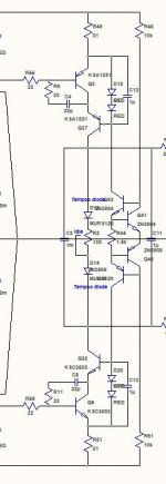
Please guys some comments about Hawksford cascode in attached circuits. Will there be any difference between a. and b. schematics performance?
I prefer the first circuit, as signal currents won't flow through the LEDs and feed resistors. The impedance at the cascode bases is also larger, so less current will flow through the resistors and make the Hawksford cascode more effective (but this might be negligible depending on the impedance of the LEDs). Furthermore, less components needed...
Increasing 10 ohm Re, let's say to 100 ohm will decrease OLG significantly. Isn't the main objective of tracking cascode to hold Vce of VAS gain BJT at constant potential to eliminate Cbc potential variations and thus make distortions independable from bandwidth? How does the value of Re influence enhanced function of tracking cascode? 

The other function of the Hawksford cascode is that the base current (thus all Early and Cbc currents) enter the cascoded transistor's emitter and then the cascode transistor's emitter, so the cascode "drives itself". This cancels all Early and Cbc currents, giving the cascode an extremely high output impedance. However Re needs to be large so the small base currents are confined to the emitter. It is the same principle as the Baxandall cascode.
Now that I think about it there won't be much benefit in this circuit of a large Re because the cascodes are feeding a low-impedance common-emitter stage, so it will probably be negligible.
The cascodes could easily be turned into Baxandall cascodes, rather than increasing Re, but this would probably not bring any technical benefits.
Lazy....I can't show the center part..as it is not mine to give away.
So modified SSA base core is a secrecy.
Hopefully someone clever will make big-bucks out of it. Flood of producers and competition between them demands new models almost every month and it wouldn't surprised me if one of the amps on the market will be SSA based. At least it would be nice to listen to that one ...

You mean you want us all to agree on one design !
I'm not even sure it would be desirable - I understood there are certain compromises inherent in chip design.
No, I just mean lets not make the reference design very large parts count, find a golden section for it so it would be fairly economical and easy to build, trim, and service, if out on PCB from AndreJ at a point. Making it into a chip was a funny way to say it accumulates so many parts with any new idea added. Nobody can order a chip GB, else we are a million.
The way we go we would need to sign a petition to Scott Wurcer for shrinking the amp into a chip for us in the end.
Hi Salas
Don't worry SSA BIGBT HP 1.9 has all the major parts needed already involved in the schematic. What's left is a matter of fine tuning the parts values and their small geo reconfigurations according to sound checks, listening and measurements results at the end.
Last week I was working, don't get me wrong hehe only a few hours not the whole week, on gate stopper resistors and by performing the measurements I noticed the scope waveforms to be more confident, less HF nervous (at 10 mV/100 ns region) also the output impedance immediately went down from 5,6 to 4,7 mohms/20 kHz (less work for the feedback) and at the end listening tests also proved the sound to be better.
What can I tell you, for me personally I am at the max parts count for sure but if someone would put the front-end into a silicon wafer ... why not.
P.S. I almost forgot to tell you guys, all four zeners on my SSA PCB are TL431.
Last edited:
Ahh... the SSA signal path is based on the monster, so in all fairness everything comes from somewhere..In these simple circuits.. the housekeeping is everything.
When working with driven cascodes you have the task of separating the voltage and the current..sometimes a simple resistor is good enough when you want to keep a certain fixed but dynamic spread as in the VAS cascode. other times you're better fixing the LED current with at CCS
When working with driven cascodes you have the task of separating the voltage and the current..sometimes a simple resistor is good enough when you want to keep a certain fixed but dynamic spread as in the VAS cascode. other times you're better fixing the LED current with at CCS
So i suppose we are at a nice minimum of current provided by the driver stage.
I prefer a "maximum" value there hehe
Look at the drive in the Goldmund Mimesis 3 for example.Well, one thing can be done to save some power and add some roughness would be to reduce the rail to rail voltage of the power stage ?
Never thought about it. The biggest reluctance for me to build your SSA_Crescendo comes from the 70V supply transformer which I don't have (I have only one big 20A transformer for PA amp project). In the past I have lowered the supply rail of the original Crescendo and the result was not good. So for 70V I have to parallel/series two or four transformers, something that I will do only if the amp is spectacular. Now I think I can "reconfigure" your amp for 56.56V (40VAC) supply (at least for the rear end), keeping the "parameters" unchanged as much as possible.
BTW, all the SSA-amp I found in this thread, including yours, tend to have a horrible simulated performance
I know it doesn't tell everything, but I have simulated many amps, and my favorite amps or the top amps by coincidence have very good simulated performance Thanks Christophe.
Please guys some comments about Hawksford cascode in attached circuits. Will there be any difference between a. and b. schematics performance?
I will prefer [A] just by intuition. From building experience I found that I don't like typical circuits when it is connected to ground instead of floating to the opposite rail. For output driver (EF) I definitely like floating one. For cascoded VAS I like it floating also (such as done by Accuphase, not grounded as in Crescendo). May be this is related to available noise in the ground level, but may be not as I think I prefer an LTP constant current source connected to rail instead of ground (assuming that rail has higher noise).
For VAS the cascode must be floating, if you ground it like suggested in b. The 10 Kohm ground resistor sets the led current. When the signal is present the voltage varies over that set resistor, which in turn modulates the led current and thus modulates the spread in the casode voltage. That would remove any gains from placing it there in the first place..so either the connected resistor or as I suggested a high-impedance floating current scouce. 1mA Supertex depletion mosfet would make a rather nice choice.
Ahh... the SSA signal path is based on the monster, so in all fairness everything comes from somewhere..In these simple circuits.. the housekeeping is everything.
Glad you choose this amplifier topology for the speakers product line of your company, well known from their transparency and musicality. It will be a very nice match since SSA is not unpleasant at any musical programme. I just listened to SSA for a few hours and I am really impressed what can be achieved with such simple input/diff stage with practically one BJT pair managing everything. If you will do good housekeeping, and from what was seen you certainly will, than your speakers will be very pleased.
- Status
- This old topic is closed. If you want to reopen this topic, contact a moderator using the "Report Post" button.
- Home
- Amplifiers
- Solid State
- Simple Symetrical Amplifier