For those who may have missed it, here is a re-post of my favorite link for the SMD process. It was very helpful to me and may be aslo for others new to the subject.
Surface Mount Soldering 101 Video
Surface Mount Soldering 101 Video
I've used this Mouser code: 910-SMD291NL
For those who may have missed it, here is a re-post of my favorite link for the SMD process. It was very helpful to me and may be aslo for others new to the subject.
Bob, that video is a classic must

It's thank to it that I've learned about Chip-Quik fantastic products, particularly the desoldering alloy.
BTW components in the Fremen Edition are not difficult to solder, they're quite big for SMD...
An update on resistors:
BOM's KOA 390R carbon film is pretty good, maybe better than the Takman (but not than the Riken) for that position (more balanced timbre).
Yet evaluating though, as for the 100K input shunt, an MK132 seems to make wonders there, next week I'll have the KOA carbon film, let's see...
Those Takmans seems too much colored... no way...
Final build?
Dear Dario, great work as usual!
How is the beta test going?
I will be interested to purchase boards and (kits perhaps) to build when you get into final production stage. The My ref Rev C ultimate BOM I built still sounds great, but time to build again soon I think!
I'll 'lurk' until your beta test is over!
Cheers
Bill
Dear Dario, great work as usual!
How is the beta test going?
Hi Bill, thanks
Beta testers are ready but have yet to begin.
I think next week will come the first feedbacks.
I will be interested to purchase boards and (kits perhaps) to build when you get into final production stage.
Fine
I'll 'lurk' until your beta test is over!
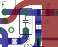
What is the purpose of 4 diodes bav99 and zenner 27v connected between output of opamp and power output ? I think this is new in your My_ref FE version.
It's a safety measure, a voltage limiter that pemit use of higher rails on LM318.
The idea come from the My_Evo.
Also what is that SJ1 symbol connected to pin 7 of LM3886.
It's a solder jumper that allows different grounding of mute circuit of the LM3886:
To AGND like in the Rev C or to GND like in My_Evo Rev A.


Hi Bob,
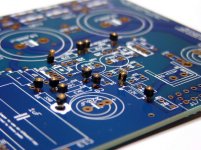
nice soldering work
Do you plan to use Black Gates for C9? If so C21 shouldn't be mounted.
C103 and C203 are optional, it would be better to desolder them, but possibly they don't harm either.
Maybe you can desolder them after the build is completed so you can report if removing them sounds better (It did in my case)
Dario, my plan was to do a "standard" build so I can hear the changes as I upgrade. But I'll follow your advice on the best path to take.
I almost made a post earlier today to request an explanation of C103 and C203 and I'm still not quite sure of their function. I looked back on the threads but couldn't zero in on anything. Info Please
I almost made a post earlier today to request an explanation of C103 and C203 and I'm still not quite sure of their function. I looked back on the threads but couldn't zero in on anything. Info Please
Dario, my plan was to do a "standard" build so I can hear the changes as I upgrade.
Fine, C21 is needed then, just remember to remove them when and if you'll mount the BGs in your upgrade path.
I almost made a post earlier today to request an explanation of C103 and C203 and I'm still not quite sure of their function. I looked back on the threads but couldn't zero in on anything. Info Please
C103 and C203 have the same function of C5 in the My_Ref RevC (removing spikes from bridges) but using soft recovery diodes they're not needed.
In fact, if you ground the LM3886 to GND (the better sounding solution, IMHO), the amplifier sounds better (more dynamic and full) without C103/C203, at least in my system.
I've left them as optional in beta boards to let people test them (maybe different transformers than mines need them).
I remember the GND discussion but wasn't sure how it was resolved. I'll be getting all the "top shelf" parts a little later.
Just remember to short one of the two posistions of the solder jumper with a solder bubble.
I suggest you to use the PGND one but you can change it in any moment desoldering the bubble and shortening the other posistion, your choice.
Thanks
You're welcome
Attachments
Last edited:
1N5244B & KOA resistors
Just mounted them and they work very well in circuit.
1N5244B sound as full as BZX85 with tighter bass and, maybe, slightly more refinement.
I've also tried the industrial KOAs indicated in BOM (with the exception of R13, now a KOA carbon film) and they sound incredibly good.
R13 as KOA CF sound very good, maybe the MK132 is a bit more precise and refined but also more closed... it will be a difficult choice but price/performance is toward the KOA.
Probably using low price audiograde resistors like PRPs and Takman isn't necessary at all, difference it tiny and matching their coloration is difficult.
The TX2575 has a clear advantage over the KOA MF but at a enormous price difference...
I'll try IRC RC55Y precision resistors: they're 15ppm, non magnetic and they cost less than PRPs.
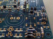
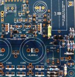
Installed resistor sockets as described by Dario.
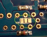
Couldn't tell if indicated spot is an allowable bridge or if it's just a super close tolerance.


Not sure if these photos should be posted here or on the other thread ????
Couldn't tell if indicated spot is an allowable bridge or if it's just a super close tolerance.
Not sure if these photos should be posted here or on the other thread ????
Attachments
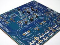
Installed resistor sockets as described by Dario.
Couldn't tell if indicated spot is an allowable bridge or if it's just a super close tolerance.
...
Not sure if these photos should be posted here or on the other thread ????
Don't worry Bob, these pads are on the same track so no problem if they bridge (see attachment).
And yes, this is the right thread
Attachments


The D105/D205 diodes I got from Mouser are glass (1N5244B) and those in your picture are not (1N5351BG). If I use the glass do they need to be raised above the board as on the MyRefs for ventilation?
I don't think they need to be raised since they dissipate barely one tenth of their rated power.
Now I'm using too 1N5244B and they're not raised, no problems so far.
Just one note on transformer wiring, since I didn't wrote anything about it.
The transformer should have double 25V (24V also fine) secondaries, let's say:
Secondary 1: green/yellow
Secondary 2: violet/white
They should be branched that way:
Green to AC1, Yellow to NAC1
Violet to AC2, White to NAC2
- Status
- This old topic is closed. If you want to reopen this topic, contact a moderator using the "Report Post" button.
- Home
- Amplifiers
- Chip Amps
- My_Ref Fremen Edition - Beta build/Fine tuning