LC,
I would really like you to discuss with you about my protection circuit. And to see his "failure" detection part in your final circuit.
Because it is beautiful, and had proven his efficiency on the worse conditions and different amps for decades, in the worse difficult situations (Big PA systems).
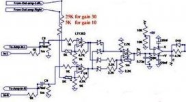
The idea is simple. Instead of analyzing the output signal, integrating-it to detect DC in output etc.. witch is slow and complicated, i just compare input and output signals.
If any difference (a working amp is supposed to be a strait line with gain) you can detect-it instant.
The theoretical circuit is very simple. First, you adjust output signal to the same level than the input one (inverse of the gain amp). Then, in an OP amp or a comparator, you make the difference (you can give some gain on this differential signal if needed).
With a second op Amp, you rectify the error AC signal.
Then,you just have to chose the threshold witch will fire your protection.
This error signal is very interesting, in real world, to see how bad is an amp with a loudspeaker's charge on transients signals ;-). An interesting tool for design too.
This simple and economical circuit will detect instant (µs) everything that can happens bad in an amp: HF oscillations, (even only on transients), DC, and, of course, short circuit on the output. It can use only a double op amp and few resistances around for 1 channel, or 3 amps for 2 channels.
One schematic to illustrate here:
http://www.esperado.fr/images/stories/protection-totale-definitive-mini.gif
(Do not take care of my relay command and power-on delays parts)
Fell free to use-it as you like, if you like. You best original amp need the best original protection. ;-)
Hi Esperado

This part of it, if proven as you've said, is really a pearl. As you probably know I use SSA Soft Start utility module, mainly designed for push-button switching-on, soft-start, trigger in/out etc. but it also includes small protection part as DC sense only but it can be upgraded with your in/out comparator circuit any time. That at the end would result in a perfect amp utility "all in one" PCB module. It can be our next small mutual project to give to DIY Audio.

Attachments
You will see the zobel resistor smoke
I built my SSA first time round without any major flaws (in other words basically functional) and this was using proto-board.
My zobel resistor smoked and the first option I had was to fool around with capacitors values across the feedback resistors. once stable then one can start tweaking because if you find a problem you can go one step back and look from a different perspective.
Spice did tell me that there is a possibility of oscillation so I expected that in practice there may be. Problem is that spice uses small signal characteristics and oscillation may appear for many other reasons, such as at high volume, high temperature, imbalance in lumped constants, signal coupling between PCB track, all kinds of junk that one can only really establish under dynamic conditions.
If you have not got any decent test equipment, you may still achieve the subjective "sounds absolutely astonishing" results, but these cannot be objectively verified, while your simulator may predict the best or worst performance is really irrelevant.
What is important is that it sounds good to you because you will be using it. Chances are that only 0.5% of the people on this forum actually like the sound of Lazy Cat's SSA on their particular speakers.
The amp, by itself, doesn't make any sound, nor does the speakers, it's the combination of the two that sounds great or mediocre, regardless of simulator results.
Hi Nico
I share the same opinion regarding soulmate feelings with you so surely it's recognized in amp's & music taste as well. SSA, when tested basic version I immediatly recognized potential winner for my selection for the next years amp-mate. Now SSA BIGBT HP still uses the same basic core and with few supporting parts enables it to shine in its full glory. I am in concluding phase to finish this project and I know after revealing some more important informations many will go to walk on the same path. Until than all the best to you Nico, enjoy
I have seen this simple amp. evolved as time pass by.one thing that bothers me is the v12 version.on a supply 0f 50v compared to symef which uses 2pairs and actually works for me.surely I can build 3 amps of symef versus a single channel of this v12 using 50v.Is there something I missed thats needs to be enlightened?
regards,
joel
Hi drowranger
You miss nothing, V12 would be a beast with a romantic heart. If really decided to built it, I can of course help with all thermal stability considerations informations needed. Regards, Andrej
Last edited:
Nico, would you say your version of the SSA is ready to a novice diyer without an osciloscope to build?
Hi PauloPT
Oscilloscope is a must and most useful instrument for one DIY-er building the amps. I really recommend you to buy one second hand Tektronix scope and than you will actually see what is going on at speaker output.
oscilloscope?
this amp is not simple anymore...I will still prefer the SSyMEF(simple symmetrical emitter follower) with two pairs of output on a 50v supply
regards,
joel
Hi PauloPT
Oscilloscope is a must and most useful instrument for one DIY-er building the amps. I really recommend you to buy one second hand Tektronix scope and than you will actually see what is going on at speaker output.
this amp is not simple anymore...I will still prefer the SSyMEF(simple symmetrical emitter follower) with two pairs of output on a 50v supply
regards,
joel
this amp is not simple anymore...I will still prefer the SSyMEF(simple symmetrical emitter follower) with two pairs of output on a 50v supply
regards,
joel
Then why bother?
Indeed the SYMEF is a very pleasing amp to me. It has a lovely mid range, one of the best I have ever heard. But the SSA arouses me curiosity, I'll built it some time in the future when I buy a scope. The reason I didn't buy a used one yet from eBay it's the shipping costs, more than the device it self costs. Anyway, it's in my to buy list for the near future.PaulPT, you built Harrison's SYMEF and you were over the moon - that is absolutely great, stick with it
For the time being, if I wanted to use the sound card as a scope does a simply resistor divider at the amp's output be adequate for input card protection?
Free shipping
RIGOL DS1052E 5.6" TFT LCD 50MHz 2-Channel Digital Color Storage Oscilloscope - Free Shipping - DealExtreme
http://www.dealextreme.com/p/ut61e-2-6-lcd-digital-multimeter-red-black-1-x-9v-6f22-battery-113306
Local
http://pt.farnell.com/gw-instek/sfg-1013/function-generator-dds/dp/1563805
You won't find better performance to money ratio items than those 3 above nowhere for a while.
Very good precision and 22000 counts, bandwidth, true rms ac, logs to pc, but don't stick it to high energy rigs like in doing building electrician's work, only Flukes and Agilents for that. Although it has some MOVs and PTC and HRCish fuses, its not proper for the CAT written on its face.
Thanks for your appreciation. (Yes it was the part i was talking about ;-).Hi Esperado
This part of it, if proven as you've said, is really a pearl.
Proven ?
It need some comments. Using fast op amps (to minimize phase errors) you tune the gain to reach the minimum differential signal.
Then, even with a very powerful low distortion, low impedance power amp with a large over sized power supply, you will see amazing errors on kick drums, listening to music with your speakers.
This can bring the protection to fire at each kick, even at surprising low level..
This will change your mind about the way our "fidelity" dreams are turning in real life ;-)
That the reason why we need to tune a threshold.
This threshold can-be sensitive enough to let the protection fire if the amp saturate, even very few. But you can let some margin, as it depend of the loudspeakers and filter impedance curves and efficiency (moving coils currents).
It with fire with any oscillation (or DC offset, or parasitics), far, far before it can damage the most sensitive tweeters or amp parts. (if the protection can cut the output fast enough)
It will protect the amp for output short circuit even at very low level.
At the time i had this idea, i had made many demonstrations, trying to sell-it. Hundred of output short circuits at various musical levels. With never a failure, never a noise.
And, on my personal amp, my protection circuit using this idea run since decades.
Because it fire instant at low DC offsets, it will protect the system from commutation clics at power on/power off. The loudspeakers will be disconnected during them.
Of course you will add a delay before loudspeakers will be connected again after protection had fired.
On my amp, the loudspeakers are not connected at power on until the original delay is passed and the protection will wait for any DC stabilized before connecting them. On power off, loudspeakers are disconnected instant., long before power caps had been discharged. No slightest noise or clic can be heard at all. I had added a delay to limit the power supply current during the time it charge their big caps. And an other static relay to protect the amp (direct coupled) from any DC in the input
I use this comparator circuit idea as a measurement instrument, looking to the error signal with my oscillo, to evaluate all my amps on the test bench. It is very helpful.
Last edited:
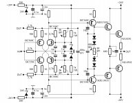
LC, as the part of your protection witch cut the output signal is part of the amp itself, (as you said, i use mine as an universal circuit), may-be we can simplify further this idea.
May-be we can take the differential signal at the input stage's emitters, and, so, get rid of the differential stage itself and the input/output levels balance fine tuning ?
May-be we can take the differential signal at the input stage's emitters, and, so, get rid of the differential stage itself and the input/output levels balance fine tuning ?
Awesome! Very good work Lazy Cat!
Ive been reading this thread for many many hours wthout result because its over 2000 posts!! Very nice but in a way difficult to sort out the important information.
Could anyone supply me with the schematic Lazy Cat used in his final product, which post is it?
I saw Salas remaking the first Simple schematic. Did Salas or anyone manage to get a good result without adding any caps in signal way?
Many questions... What would be needed to make to use +-42V smps? My plan is +-42v 400w smps...
Im very interested in using the Exicon trannies mentioned in the first schematic... Anyone tried it with them?
Thanks!
/GM
Ive been reading this thread for many many hours wthout result because its over 2000 posts!!
Very nice but in a way difficult to sort out the important information.Could anyone supply me with the schematic Lazy Cat used in his final product, which post is it?
I saw Salas remaking the first Simple schematic. Did Salas or anyone manage to get a good result without adding any caps in signal way?
Many questions... What would be needed to make to use +-42V smps? My plan is +-42v 400w smps...
Im very interested in using the Exicon trannies mentioned in the first schematic... Anyone tried it with them?
Thanks!
/GM
here you are (however schematic is related to amplifier portion only, not including soft-start, DC sense, etc) :Awesome! Very good work Lazy Cat!
Ive been reading this thread for many many hours wthout result because its over 2000 posts!!
Could anyone supply me with the schematic Lazy Cat used in his final product, which post is it?
http://www.diyaudio.com/forums/solid-state/193923-simple-symetrical-amplifier-199.html#post2922818
Awesome! Very good work Lazy Cat!
Ive been reading this thread for many many hours wthout result because its over 2000 posts!!
Could anyone supply me with the schematic Lazy Cat used in his final product, which post is it?
I saw Salas remaking the first Simple schematic. Did Salas or anyone manage to get a good result without adding any caps in signal way?
Many questions... What would be needed to make to use +-42V smps? My plan is +-42v 400w smps...
Im very interested in using the Exicon trannies mentioned in the first schematic... Anyone tried it with them?
Thanks!
/GM
Hi, the experimental LATFET amp with 3 stabilizing Jfets works and plays but I am in the thinking of a servo to free it from periodic re adjustments due to changes of ambient temperature bcs of seasons or environment.
There is Bigun's TGM5 to contemplate too which is Sziklai also but all BJT, finished, has BOM, and of course has LCSSA input topology. http://www.diyaudio.com/forums/solid-state/196973-tgm5-all-bjt-simple-symmetric-amplifier.html
LC, This is the following amplifier i;m going to do. Should rated maximum at 120W @ 4ohm for my situation.
I'm planning to build it in 3 layers (very small board). About on 3board of 4.5cm X 9cm.
First board will consist of Main reservoir(28V) with OPS.
Second board will consist of secondary power(20V) circuit and VAS.
Third will be input stage with its power circuit (15V).
I want to ask, for a typical toriod, what is the distance from it to circuits ? (not effected by the magnetic field )
Attachments
It just depends on the resistance of the wires.I'm planning to build it in 3 layers (very small board). About on 3board of 4.5cm X 9cm.
First board will consist of Main reservoir(28V) with OPS.
Second board will consist of secondary power(20V) circuit and VAS.
Third will be input stage with its power circuit (15V).
But your project to split your amp in several board is affraying. 1/2cm more on the tracks of the power FETS of mine transform-it in a 150w HF oscillator !
Remember that we are on Mhzs and wires (or track length) are inductances.
By example, non symmetry on the output lines and specially if the point where you take your CR and output connector is not in the middle can increase the distortion by a factor of 10 !
Last edited:
I think he means one 3 layer board rather than 3 separate boards. Thinking through the possible interactions between the layers would be essential. Perhaps going to five layers with 2 ground planes between the others might actually be simpler ? ? ?
The other feature that allows more compact layouts is having components mounted on both sides of the board.
The other feature that allows more compact layouts is having components mounted on both sides of the board.
Yes. Each time we design a strait line in a circuit, we have to FEEL the equivalent resistance/capacitances/inductances added.Thinking through the possible interactions between the layers would be essential..
- Status
- This old topic is closed. If you want to reopen this topic, contact a moderator using the "Report Post" button.
- Home
- Amplifiers
- Solid State
- Simple Symetrical Amplifier