I built up a set of these for my amp and tested them and they seem to function. I can't detect any ripple on the output with my 465. They survive power cycles, etc. I guess the real test will be to watch the output when it is powering an amp that is playing loud music. That won't happen very soon as I am a slow worker.
PM me if you want to participate in the group buy or do I need to start a thread in the group buy? Anybody know proper forum etiquette on group buys, I've never led one.
I also have suggested parts and can offer tips on how to solder the surface mount parts without buying expensive equipment that I can post here if anyone is interested.
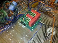
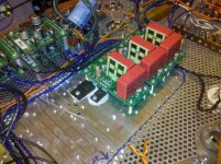
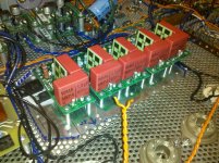
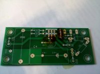
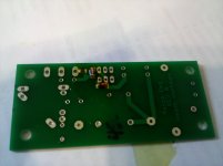
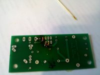
Attached are some pictures of how it all went together. This is for a push-pull amp with power supply voltages at +450(power tubes), +500, +380, -300, -420. I decided to do a split supply on this which proved interesting. I have a power transformer for the power tubes and one for the split supplies. I guess I could post a power supply schematic for those curious a bit later.
PM me if you want to participate in the group buy or do I need to start a thread in the group buy? Anybody know proper forum etiquette on group buys, I've never led one.
I also have suggested parts and can offer tips on how to solder the surface mount parts without buying expensive equipment that I can post here if anyone is interested.
Attached are some pictures of how it all went together. This is for a push-pull amp with power supply voltages at +450(power tubes), +500, +380, -300, -420. I decided to do a split supply on this which proved interesting. I have a power transformer for the power tubes and one for the split supplies. I guess I could post a power supply schematic for those curious a bit later.
I'm in.
I would suggest that you post here the price and all build info like material list, smd soldering tips and so on. Also would be interested in test data, like how much power it can dissipate with only that flat plate as heat sink.
Perhaps others who have done group buys can advise on that part.
I would suggest that you post here the price and all build info like material list, smd soldering tips and so on. Also would be interested in test data, like how much power it can dissipate with only that flat plate as heat sink.
Perhaps others who have done group buys can advise on that part.
Alright, I'll work on getting more info out.
I don't want to send these things one and two at a time so I was thinking I would charge $3 apiece for five or less and $2 apiece for 6+. Surprisingly, $2 apiece is still slightly above my cost. I like this board maker.
Attached is my power supply schematic. I will work on a material list. Obviously, the circuit values depend on design input and output voltages so it is a custom thing but really not that hard. I have suggestions as to what part series to use for certain locations like that thick film resistor on the top and caps, zeners, etc. Most are just whatever axial power resistors I could find for the lowest price.
Attachments
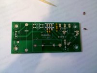
Here are some soldering tips. Basically, my strategy for soldering the SMT diodes and resistors (6 total per board) is to first paint some flux onto the pads(some use flux pen, I use a nail polish bottle). The next thing I do is pin the component with a toothpick. Next, I get some solder on the iron's tip. You don't need very much. I then touch the tip of the iron to the metal part on the end of the component and the pad at the same time. The flux makes the solder go where it is supposed to go and as long as you make contact with the pad and the lead at the same time it will work.
If there is too much solder afterward you can clean the tip, put more flux on and pull solder off with the iron but solder the second side first") . You can also add more solder the same way. Flux is your friend but remember that you should clean it off later. I have attached pictures of the results of doing this at home. This was all done with the standard tip that came on my Weller iron.
. You can also add more solder the same way. Flux is your friend but remember that you should clean it off later. I have attached pictures of the results of doing this at home. This was all done with the standard tip that came on my Weller iron.
If there is too much solder afterward you can clean the tip, put more flux on and pull solder off with the iron but solder the second side first
. You can also add more solder the same way. Flux is your friend but remember that you should clean it off later. I have attached pictures of the results of doing this at home. This was all done with the standard tip that came on my Weller iron.Attachments
Also would be interested in test data, like how much power it can dissipate with only that flat plate as heat sink.
I forgot to answer this. The plate in the picture actually has some nice big fins sticking out on the top side of the chassis. It's a heatsink I salvaged from a big industrial motor driver.
Anyway, the max dissipation is going to be set by the heatsink/mosfet combo. My method is to go overkill. I bet this won't even get too hot to touch. I use FQAF11N90C for positive supplies but you could use a cheaper one I suppose. I like the isolated package, but it is a little pricey too. I also found an LM317 with an isolated package. For the negative supplies I did have to buy rubber insulators for the LM337 and p-channel fet to isolate them.
I'll get a list of the noteworthy parts that I used on Monday.
Of the SMT components, there are four diodes and two resistors. In the schematic in post#7 the diodes are D1, D6, D8, and D9. I used 15V zeners for all of these in my design. I just noticed that I goofed on the schematic and D9 and D1 don't have the symbol for a zener. They are meant to be zeners. I will get some part numbers at work tomorrow and post a BOM tomorrow evening hopefully.
The two SMT resistors are 0805 and are R1 and R2 in the schematic. R1 is a gate stopper obviously and needed to be small to fit where I wanted it to. R2 I made 0805 because it is easy to get any value you want in high precision and low cost. My plan was to build it up and see how close I came to my target voltages and swap that resistor if necessary. Most came within a volt or two but one was 9V off. I may swap next time I order parts. R4 is a 5% power resistor so I knew this might happen.
The two SMT resistors are 0805 and are R1 and R2 in the schematic. R1 is a gate stopper obviously and needed to be small to fit where I wanted it to. R2 I made 0805 because it is easy to get any value you want in high precision and low cost. My plan was to build it up and see how close I came to my target voltages and swap that resistor if necessary. Most came within a volt or two but one was 9V off. I may swap next time I order parts. R4 is a 5% power resistor so I knew this might happen.
Here is my procedure for designing a Maida regulator. I will insert example mouser parts numbers that I used for a 450V regulator with a target current of 290mA. I probably don't do things the best way and welcome any comments on my method. First you need to pick the polarity, voltage, and current requirements for your regulator. If you are building a positive regulator, you will use an LM317(513-NJM317F) and N-channel fet(512-FQAF11N90C). Follow the diode polarity on the schematic. If you are building a negative regulator, you will use an LM337(512-LM337T) and a P-channel fet(512-FQP3P50). Reverse the polarity of all of the diodes (and caps if you use polar caps). LM337/LM317 do not have the same pinout. Make sure you put your regulator in the right place. The mosfet can be TO-220, TO-247, TOP-3.
1. Diodes: D1(78-TZM5245B-GS18) is normally out of the circuit and at the moment I am having trouble figuring out why it is even there. I think I put it there because Morgan Jones did, but I think he put it there because he bypassed the input pin on the LM317(which I am not). It is not in the Maida app note. Anyway, it's purpose is startup/shutdown protection, just make it the same as D9(78-TZM5245B-GS18). I picked a 15V zener for D9 so that with the drop through the mosfet and R8, I would still have about 9V across the LM317. D3 and D7(583-1N4007-B) are 1N4007 and are there for startup/shutdown protection. D2 and D4(78-TZM5245B-GS18) are there to protect the gate of the mosfet at startup/shutdown, use 15V zeners for most fets(unless the gate-source breakdown voltage is less than 15V). D8 and D6(863-1N5388BG) I use when the mosfet is rated less than the raw supply voltage. This really only happens when I build a negative supply since they don't seem to make 900V p-channel fets. I use two 200V 5W zeners here since I am using a 500V mosfet. I'm not sure they are necessary or do anything but I put them there and I have no problems.
2. Caps: I use 1uF(505-MKP41.0/630/10) for both caps since that is what Michael Maida used. Lead spacing is 27.5mm. I haven't experimented with different values. I added extra holes on C4 so that an electrolytic cap could be used. Use at your own risk.
3. Resistors: I used a 1k gate stopper for the mosfet (R1)(292-1.0K-RC). I used a 2.7 Ohm resistor R10(660-MOX1C2R7J) and 100 Ohm for R11(660-MOS1C101J) just like in LB-47(the Maida app note). For R7, I shoot for 5mA. Subtract the output voltage from the input voltage and 15 more volts for D9 and that will give you voltage across R7. You know current and voltage, solve for resistance. Make sure you get a resistor with adequate power rating. Same thing for R2(292-140-RC) and R4(588-TA310PA50K0JE). I shoot for 10mA through R4 to ensure the regulator will regulate with no load. Subtract 1.25V(LM317 reference voltage) from output voltage to get voltage across R4. You know voltage and current so can figure out resistance, pick nearest value. I used 50k for a 450V supply for example. I found a big thick film resistor and spaced the leads for it but smaller axial resistors could be used here. Now calculate the exact current through R4 with the actual resistance value you will use. The LM317 forces 1.25V between the output and adjust pins so pick R2 using the current you just calculated. You should be able to find a resistance very close to what you calculate. R8(660-MOSX3CT521R5R1J) is a current limiter. Its effectiveness is limited. I pick a value such that there is a 1-2V drop at the target current for the regulator.
4. Other useful parts: I use these(534-401) spacers to mount the boards. They are tall enough to clear the mosfets of another regulator but short enough that the leads reach through the board when mosfet/regulator are mounted on the heatsink. I drill and tap the heatsink and use a long screw to go through the board and spacer. I use these(151-101-RC) test point loops to connect input, output, and ground to the board. I prefer soldered connections over connectors.
Notes:
Maida regulators apparently don't like capacitive loads. Don't build this regulator if you intend to tack a 100uF cap on the output. Also, if you short your output to ground you will probably kill the semiconductors in this regulator. See http://www.national.com/ms/LB/LB-47.pdf for more information.
Let me know if you have any questions.
I shoot for 10mA through R4 to ensure the regulator will regulate with no load.
That's a lot of heat at 500V. I have a couple suggestions:
1. Regulation is spec-ed @10mA but min current is 5mA max. What happens between 5 & 10? No regulation? What happens <5? Blows up?
I'll probably burn a few finding out.Anyway, I would look for a regulator that requires less quiescent. I know LT3080 only requires 1mA, there may be others.
2. Another alternative is to put a "load" resistor elsewhere in the amp where it can dissipate and not heat up a bunch of other components.
Maida regulators apparently don't like capacitive loads. Don't build this regulator if you intend to tack a 100uF cap on the output. Also, if you short your output to ground you will probably kill the semiconductors in this regulator.
Yes, minimum capacitance. But just for good measure, I'm thinking monster D6D8 of the right voltage would hold up long enough to get you into the SOA at startup. And pull enough current in a short to blow a fuse which I will so thoughtfully provide in the B+ line
Might actually work.Maida regulators apparently don't like capacitive loads. Don't build this regulator if you intend to tack a 100uF cap on the output.
You bring up an interesting point. How much is too much?
A couple of years ago I tried to build a maida regulator to use as a choke substitute. I did it on perf board and the result was something of a hash. It fouled up the room with acrid smoke and scared the dog. I went back looking for the mistake but couldn't find one. It's still around here somewhere collecting dust. I was using it with a 56uf cap IIRC, and I wonder if that might have been the problem rather than a wiring error. I was just getting ready to revisit that project when I stumbled across this excellent thread.
I'm reconsidering whether the maida circuit is really such a good idea for that application. Specifically, I'm concerned that a power supply without reasonable levels of capacitance will not have adequate reservoir for a tube amplification application. You've obviously given this plenty of thought; what is your take on this please?
check the urban dictionary
Let me re-phrase that.
Which devices are in MELF packages? I'm familiar with the SOD80 and related packages. Pad layouts can be made such that they support DO219, SOD123, or others as well.
Manufacturing instructed us to quit using them (MELFs) some eight years ago due to solder quality issues. Apparently the devices like to roll around.
If you are hand soldering them, it is not really an issue but I prefer other devices wherever possible.
You bring up an interesting point. How much is too much?
This...
Or, how much resistance is enough before a capacitor? Say, I have regulator feeding B+, plus 2 resistors w/ 2 caps behind the resistors for the next stage of the amp.
That's a lot of heat at 500V. I have a couple suggestions:
1. Regulation is spec-ed @10mA but min current is 5mA max. What happens between 5 & 10? No regulation? What happens <5? Blows up?
In my experience, what tends to happen is that you get really poor regulation if the regulator isn't loaded with the specified minimum current. Usually, the output voltage ends up being higher than the target value in this condition. Once the load current increases (as load is applied), the voltage settles at the target voltage. If your load can handle the momentary over-voltage, great. If not, then you're better off burning a bit more in the feedback resistor ladder.
Note that Mike Maida used 5 mA in his circuit (National Semiconductor LB-47).
~Tom
That's a lot of heat at 500V. I have a couple suggestions:
1. Regulation is spec-ed @10mA but min current is 5mA max. What happens between 5 & 10? No regulation? What happens <5? Blows up?
Anyway, I would look for a regulator that requires less quiescent. I know LT3080 only requires 1mA, there may be others.
2. Another alternative is to put a "load" resistor elsewhere in the amp where it can dissipate and not heat up a bunch of other components.
Yes, minimum capacitance. But just for good measure, I'm thinking monster D6D8 of the right voltage would hold up long enough to get you into the SOA at startup. And pull enough current in a short to blow a fuse which I will so thoughtfully provide in the B+ line
The LM317 itself requires less than 2mA to regulate at the voltage across it (8-10V) in my design(see graphs in the data sheet). The problem is that all the current that goes through the mosfet bias network goes around the regulator so it doesn't count, but sure you could reduce that down and get away with 5mA or maybe even a smaller load. I think MJ's book said 5mA(for the mosfet network) was good for low noise. I just went with that. I used 5mA or less for the output voltage set divider whenever there was a downstream load for example with regulators that have other regulators following them or with heater biasing networks.
As far as capacitance goes, be prepared to sacrifice some pass devices but don't let me discourage you from experimenting. I used 5W zeners and looked at the data sheet which has really good data on current pulses that they can survive. Looking at that, I think I concluded that they wouldn't survive very much capacitance but I left them in there anyway.
- Status
- This old topic is closed. If you want to reopen this topic, contact a moderator using the "Report Post" button.
- Home
- Amplifiers
- Tubes / Valves
- Maida Regulator PCB