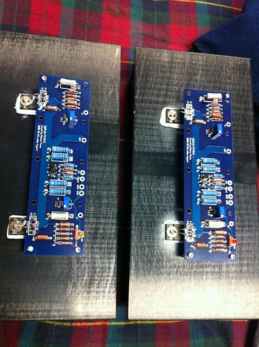
Question on the thermistors... When you bend them over to the mosfets, how do they stay in contact?
Don't glue them. You just need to make a double bend. Bend them about 1/4- 1/3 of the way up the leads and make them touch the fet. They will not be in particularly good contact, but close. Now, while touching the bends (knees) that you just made with the first fold, make a bit more bend into the leads, this will bend the lead at a different place and keep the tip of the thermistor in touch with the fet.
It's also about the last thing you do to the PCB once it's all mounted and installed in the amp.
It's very, very easy, but kinda hard to describe in text. I should shoot a 10 second video to show it.
")
What do you think about a minimalist open lattice type enclosure? The sides would be substantial heat sinks of course, but I'm thinking about tying them together with strips of aluminum instead of one large sheet. The rear would have to be substantial enough to support the jacks and such, but the top and bottom could be fairly open. Not sure what I would do with the front yet... perhaps also just a few strips of aluminum as well.
Just wanted to see what the watchouts might be before I lay it out in more detail.
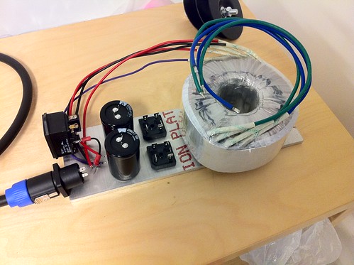
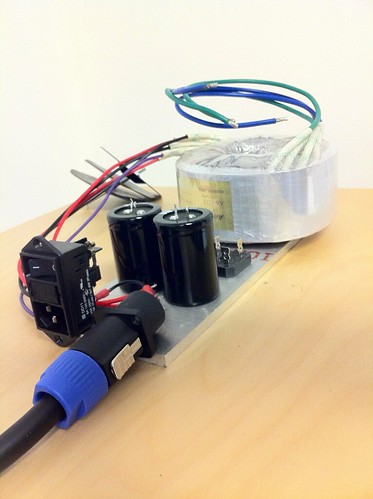
I'm also still going down the path of a separate enclosure for the trafo/rectifiers/first pair of caps. This will be located on the floor away from the amp via a 3' umbilical. For this, I was thinking it would be 1/4" aluminum plate on the bottom and rear with a wooden assembly for the front, sides, and top that would be grooved on the inside of the sides to slide onto the bottom plate. Then it could simply screw to the rear with a few screws.
Any input is welcome!
Just wanted to see what the watchouts might be before I lay it out in more detail.
I'm also still going down the path of a separate enclosure for the trafo/rectifiers/first pair of caps. This will be located on the floor away from the amp via a 3' umbilical. For this, I was thinking it would be 1/4" aluminum plate on the bottom and rear with a wooden assembly for the front, sides, and top that would be grooved on the inside of the sides to slide onto the bottom plate. Then it could simply screw to the rear with a few screws.
Any input is welcome!
Yeah briliant idea use 13 mm or 1/2 in pints aluminium rod
stick any front you / she likes
any back you think may hold the plugs nobody see that
and the rest Aluminium mesh
The sinks will hold the lot togheter
No stinking (hot) capacitors that way
And you can cut the mesh with her scisors...
Separate box can even be HIFI 2000 Jobbie and 20 A plugs for the umbilicals
those cost about £2.50 if you wan't pointer.
And same Ceramic Knobs as feet £2.50 no one see those and rounded profile slides on carpet like a dream
so no back breaking lifting those
Why Just 3 foot umbilical use more = less speaker cables and same more cRc for free if you stick same of the caps under the sinks
Last edited:
Here's a mockup with some scrap aluminum that might work.
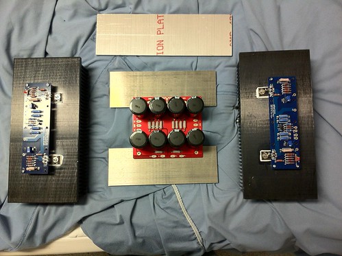
I would have one similar piece on top and on front as well probably. Then the front, top, and back would have some clear plastic attached to the aluminum to close it up but I would leave gaps at the corners of maybe 1/2" for air flow. The bottom would potentially be open.
Guess I would have to be neat about my wiring if the insides were all exposed!
Last edited:
......the fin gaps look as though designed for fan assisted cooling.
I picked up a pair of these sinks as well from Par-Metal and noticed the same thing as well. It's note 3 at the bottom of the spec sheet. I'm using these in a mini-A build.
Par-Metal
Why not make the amp box as compact as possible? What would happen if you stood the PS cap board on end and move the two heat sinks closer together? But make sure your input and output connectors are spaced and located where you like them.
Temporarily at least, the transformer box could go in a used steel sheet metal box, since it will be out of sight? (I know, "build nice, or build twice.")
Temporarily at least, the transformer box could go in a used steel sheet metal box, since it will be out of sight? (I know, "build nice, or build twice.")
Why not make the amp box as compact as possible? What would happen if you stood the PS cap board on end and move the two heat sinks closer together? But make sure your input and output connectors are spaced and located where you like them.
Temporarily at least, the transformer box could go in a used steel sheet metal box, since it will be out of sight? (I know, "build nice, or build twice.")
Hmm... I'll see if I can make that work. Makes mounting the psu pcb a little trickier and assembly too. I kinda like the wide vs tall form factor too. But I will noodle on it. Thanks for the idea!
For the trafo box, I'm thinking about doing a translam thing just for the fun of it. If I had a spare steel box lying around...
What's translam?
It's basically a bunch of layers of plywood laminated together, like a sandwich. So the bottom layer would be the front of the box with a 1/4" groove for the plate to sit in. Then, basically glue another 8-10 layers of plywood squares that I would have routed out followed by one last solid piece that the IEC and umbilical connector will be mounted to. I could also put spacers in between every third layer or so for ventilation. Or just drill out some holes.
I've considered using the technique for speakers as many have but that's too much work and wasted material for my tastes. This small box would be ok.
Here's an example.
How about a 'log cabin style' enclosure? (Is there a proper term for this? I've seen this type of construction used for wooden benches, etc.) It's kind of like a trans-lam in that it's made from layers, but would use strips (of aluminum 1/2-3/4 inch wide x 1/8-1/4 in thick?) instead of hoops (so hardly any waste) clamped together at the corners with threaded rod. This would give lots of ventilation...For the trafo box, I'm thinking about doing a translam thing just for the fun of it. If I had a spare steel box lying around...
http://sound.westhost.com/articles/diy-heatsink.htm
Like this, but taken to the extreme by also making the top and bottom from strips.
Last edited:
How about a 'log cabin style' enclosure? (Is there a proper term for this? I've seen this type of construction used for wooden benches, etc.) It's kind of like a trans-lam in that it's made from layers, but would use strips (of aluminum 1/2-3/4 inch wide x 1/8-1/4 in thick?) instead of hoops (so hardly any waste) clamped together at the corners with threaded rod. This would give lots of ventilation...
DIY Heatsink
Like this, but taken to the extreme by also making the top and bottom from strips.
Interesting idea! I'll probably stick with wood in this case since its cheaper and much easier to cut than aluminum and I don't need much cooling/ventilation for just the trafo box.
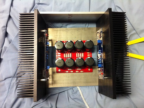
Made some progress drilling and tapping holes:
Bottom view with two pieces of Al that the PSU PCB will bolt to:
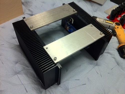
View with PSU:
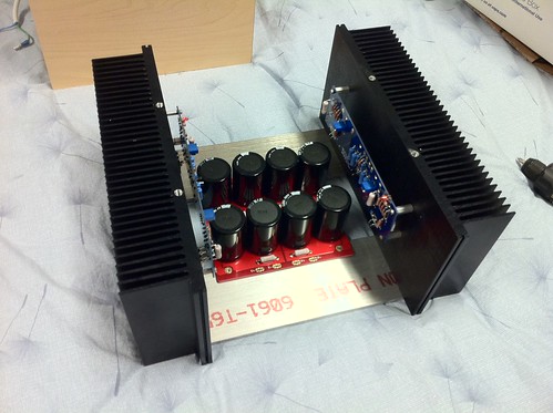
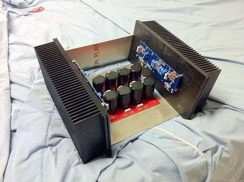
And with top in position:
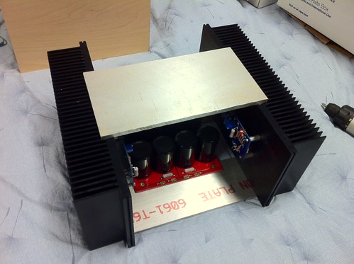
My thought is that the front and rear will have similar aluminum pieces bolted in from the side of the heat sink where there is a lip. The top aluminum piece will also have either a plexiglas or wood piece bolted to it to make up the gap to the front and rear pieces. Perhaps similar treatment from the bottom pieces. A little hard to explain so you may have to wait till another round or two of pictures to understand what I mean exactly.
Hands are sore from tapping 12 1/4-20 holes... The remaining holes may be #8 tapped as a result! Plus, just with the four bolts in it now, it's already pretty darn beefy!
Bottom view with two pieces of Al that the PSU PCB will bolt to:
View with PSU:
And with top in position:
My thought is that the front and rear will have similar aluminum pieces bolted in from the side of the heat sink where there is a lip. The top aluminum piece will also have either a plexiglas or wood piece bolted to it to make up the gap to the front and rear pieces. Perhaps similar treatment from the bottom pieces. A little hard to explain so you may have to wait till another round or two of pictures to understand what I mean exactly.
Hands are sore from tapping 12 1/4-20 holes... The remaining holes may be #8 tapped as a result! Plus, just with the four bolts in it now, it's already pretty darn beefy!
- Status
- This old topic is closed. If you want to reopen this topic, contact a moderator using the "Report Post" button.
- Home
- Amplifiers
- Pass Labs
- oneplustwo F5 build thread