A TVC is an interesting option, and the ability to add gain might be valuable with a low mu tube like the 26; my only concern is that 23 steps may not be a fine enough adjustment.
I'm also considering the P&S OPC271 opto-potentiometer. It comes as a kit that can be run off the preamp power supply or it's own supply, with >100 steps of adjustment, remote control as well as manual control, a dimmable LED display, and pre-matched optocouplers in a sealed unit. It would be pretty easy to incorporate into a new build, and would give the 26 preamp an "old meets new" kind of style. Channel-matching is not as good as a stepped attenuator, but it's still pretty good.
Check it out: P&S TECHNOLOGIES INC.
.
Last edited:
Well it's just a variant on the famous "Lightspeed Attenuator" that's been mentioned on all the audio forums. No switches or contacts in the signal path - it uses light-dependent resistors (LDR) coupled with an LED; when you vary the voltage on the LED with your volume control it varies the resistance in the LDR, which is in the signal path.
Folks swear by them as being immensely transparent. I haven't heard one myself.
I have a remote on my current preamp (motorized Alps blue pot) and it is HUGELY convenient as seemingly every CD is mastered to a different loudness. It also helps in dialing in the right volume to be sitting in your listening chair instead of standing by the preamp.
So many choices...

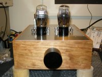
26 main chassis
I just have my 26 main chassis cut and still have to wait until the psu finished to try. I know it's way too slow, it almost takes 10 months up to here. I go with the filament bias and would like to confirm the following.
Rod,
I only have 2 16.5v 2.5A transformers. Should I go for exactly 18v ??
As of your instruction, I'll need a 1.5R 3W or more resistor for testing the regulator. Will there be any different on filament bias ??
With the 1st edition of Quanchao Sala's reg., I'll need somewhere around 145v on plate of 26. I therefore would try 170-0 in tube hybrid rectification to 32uf oil caps - 25H - 47uf pp. Would it be good for the purpose ??
Albert
Attachments
Rod,
I only have 2 16.5v 2.5A transformers. Should I go for exactly 18v ??
As of your instruction, I'll need a 1.5R 3W or more resistor for testing the regulator. Will there be any different on filament bias ??
Albert
Hi Albert,
I assume you are using Filament Bias with 10-ohm, 25 to 45W resistor, or parallel resistors.
If so, you need about 16.5V raw dc (15.5V minimum).
Your 16.5V 2.5A trafos are PERFECT for this, and even allow the luxury of some resistance right after the rectifier, which can reduce the pulsed rectifier current (reduces emissions, and is less stress for C1).
1N5822 rectifiers should still be fine. See my PDF manual ANdht01v2.PDF for tips on selecting resistors/capacitors, and how to connect the raw dc for best sound.
I have worked out a PSUD design for you -see attached.
Please test the filament bias regulator by connecting the 1.5R test resistor (dummy filament) in series with the 10R Filament-Bias resistor.
Attachments
Last edited:
I just have my 26 main chassis cut and still have to wait until the psu finished to try. I know it's way too slow, it almost takes 10 months up to here.
Fantastic looking thus far - looks to be well worth the wait !
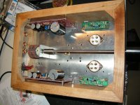
I've been tossing around the idea of moving my input selector switch to the rear of the chassis; as you have done with your volume control...The challenge I have is figuring out some sort of bushing to mount in the front plate of the chassis, so the feel of the dial does not change. Any suggestions ? Here's how I have it wired up right now. There are no breaks in the wires, I just used the terminal blocks as wire guides.
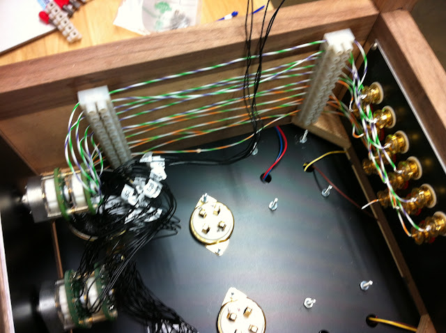
Thanks !
Hi Albert,
I assume you are using Filament Bias with 10-ohm, 25 to 45W resistor, or parallel resistors.
If so, you need about 16.5V raw dc (15.5V minimum).
Your 16.5V 2.5A trafos are PERFECT for this, and even allow the luxury of some resistance right after the rectifier, which can reduce the pulsed rectifier current (reduces emissions, and is less stress for C1).
1N5822 rectifiers should still be fine. See my PDF manual ANdht01v2.PDF for tips on selecting resistors/capacitors, and how to connect the raw dc for best sound.
I have worked out a PSUD design for you -see attached.
Please test the filament bias regulator by connecting the 1.5R test resistor (dummy filament) in series with the 10R Filament-Bias resistor.
Rod,
Many thanks for your detail reply. Lucky I ask the way to test the filament, or otherwise I would directly series the 1.5R to ground. I have 10 pcs 100R 5W wirewound parallel, but end up it's only around 9R. I got 10R with only 9 pcs parallel together, but there is only 45W. Which way I should go ?
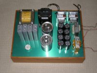
After the rectifier, my intention is 10,000uf - 25H - 30,000uf floating to the main chassis - your reg. then to ground. Would like to have your idea.
Albert
Fantastic looking thus far - looks to be well worth the wait !
I've been tossing around the idea of moving my input selector switch to the rear of the chassis; as you have done with your volume control...The challenge I have is figuring out some sort of bushing to mount in the front plate of the chassis, so the feel of the dial does not change. Any suggestions ? Here's how I have it wired up right now. There are no breaks in the wires, I just used the terminal blocks as wire guides.
Thanks !
I like your volume. Was that the 'Cat 5' cable ?
Rod,
Many thanks for your detail reply. Lucky I ask the way to test the filament, or otherwise I would directly series the 1.5R to ground. I have 10 pcs 100R 5W wirewound parallel, but end up it's only around 9R. I got 10R with only 9 pcs parallel together, but there is only 45W. Which way I should go ?
After the rectifier, my intention is 10,000uf - 25H - 30,000uf floating to the main chassis - your reg. then to ground. Would like to have your idea.
Albert
Hi Albert, For the choke, I assume you mean 25mH (milliHenry). That's OK. 4700uF is enough for C1, but 10000uF will be OK. 4700uF is better though, because the current pulses will be lower.
10R 45W should be fine, try it with this first! Make sure that the resistors are high quality though, no skimping. This is no place for White Ceramic Coffins! At least Welwyn W24 wirewound, vitreous enamelled. Andy has done lots of testing, see posts from last year.
.
Mouser, Vishay/Dale 10Ohm 55W only 6.58 USD.
HL05509Z10R00JJ Vishay/Dale Wirewound Resistors - Chassis Mount
10 Ohm 95W 17.70USD
HL09509E10R00JE Vishay/Dale Wirewound Resistors - Chassis Mount
HL05509Z10R00JJ Vishay/Dale Wirewound Resistors - Chassis Mount
10 Ohm 95W 17.70USD
HL09509E10R00JE Vishay/Dale Wirewound Resistors - Chassis Mount
For the choke, I assume you mean 25mH (milliHenry). That's OK. 4700uF is enough for C1, but 10000uF will be OK. 4700uF is better though, because the current pulses will be lower.
Yes, there was a typo mistake, a 25mH to be exact. I don't have couple 4700uf/35v, but will source them for sure.
10R 45W should be fine, try it with this first! Make sure that the resistors are high quality though, no skimping. This is no place for White Ceramic Coffins! At least Welwyn W24 wirewound, vitreous enamelled. Andy has done lots of testing, see posts from last year.
There are all Dale CW-5 in Black and from the same supplier Andy post on the thread.
Thanks
Albert
Mouser, Vishay/Dale 10Ohm 55W only 6.58 USD.
HL05509Z10R00JJ Vishay/Dale Wirewound Resistors - Chassis Mount
10 Ohm 95W 17.70USD
HL09509E10R00JE Vishay/Dale Wirewound Resistors - Chassis Mount
Thanks and will try tweaking on after firing up.
Albert,
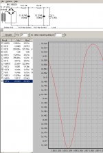
Please take the 25mH choke and measure the dc resistance with a meter. This value may need to be subtracted from the Resistor between C1 and C2 (2 ohm).
25mH may well measure 0.5 ohm or so - and mean that the 2-ohm should be 1.5.
Both R1 and R2 resistors are needed, even when the choke is used.
.
Please take the 25mH choke and measure the dc resistance with a meter. This value may need to be subtracted from the Resistor between C1 and C2 (2 ohm).
25mH may well measure 0.5 ohm or so - and mean that the 2-ohm should be 1.5.
Both R1 and R2 resistors are needed, even when the choke is used.
.
Albert,
Please take the 25mH choke and measure the dc resistance with a meter. This value may need to be subtracted from the Resistor between C1 and C2 (2 ohm).
25mH may well measure 0.5 ohm or so - and mean that the 2-ohm should be 1.5.
Both R1 and R2 resistors are needed, even when the choke is used.
Rod,
The resistance is 0.4 ohm. So I should put the choke right after/ series to the rectifier then to C1 - 1.5 ohm - C2.
Regards
Albert
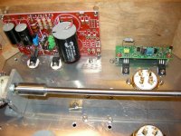
BTW I replaced the R8 to 470 ohm and C1 to 33uf /50v on the supply board. Is 33uf good for the job/ or I should keep the value 47uf ??
Use the 25mH in series with the R2 position (shown on the PSUD2 schematic, above). Not at the rectifier.
If the board has 47uF/35V - that is best.
Rod,
On #1627, I presume R1 is the 25mH choke I talked about, R2 would then be 1.5 ohm.
I don't have 47/35v. I have some 100uf/25v, 56uf/25 or I can parallel one more 33uf/50v to make it 66uf/50v. What do you recommend ??
Albert
- Home
- Amplifiers
- Tubes / Valves
- #26 pre amp