More burning in..
Should I start the clock again or do I add in the 5 hours already done ???
Tony.
I would give them a day "restart the clock" 12 hrs to burn in added to the 5 you have already should be OK ..
")
Why not put a switch on the HT LV side(switch off) Tx so you can burn in easily if you want to..
(You could put it inside the chassis.)Its not a good Idea to turn on the HT with the heaters already running though the surge is huge..and could damage the speakers. (just useful..you could just pull a fuse)
Regards
M. Gregg
Last edited:
Just a thought,
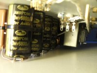
Regards the caps in the PSU its got to be worth trying the ones you have now..you have nothing to lose..
Get it working and upgrade if you think its worth it..
Perhaps drop a scope on it with a dummy load check its stable if you don't have a scope to hand see if the load gets hot with no signal..If it does something is wrong..
Regards
M. Gregg
Last edited:
Russian Tubes
Hi,
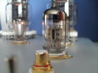
I just couldn't resist plugging in the rest of the tubes..
Once the output tubes are burnt in, isn't that the end of it or do you mean a switch just for burning in future tubes ?
In his article Tim heats the pre /driver tubes all the time and then switches the H.T. plus the output tube heaters on all together, he says that his amp has been reliable so I intend to go with this as per the schematic.
Is there any point in keeping the pre/driver tubes heated as surely they will conduct first anyway ? ? ?
Tony.
Hi,
I just couldn't resist plugging in the rest of the tubes..
Once the output tubes are burnt in, isn't that the end of it or do you mean a switch just for burning in future tubes ?
In his article Tim heats the pre /driver tubes all the time and then switches the H.T. plus the output tube heaters on all together, he says that his amp has been reliable so I intend to go with this as per the schematic.
Is there any point in keeping the pre/driver tubes heated as surely they will conduct first anyway ? ? ?
Tony.
Attachments
Hi,
I just couldn't resist plugging in the rest of the tubes..
Once the output tubes are burnt in, isn't that the end of it or do you mean a switch just for burning in future tubes ?
In his article Tim heats the pre /driver tubes all the time and then switches the H.T. plus the output tube heaters on all together, he says that his amp has been reliable so I intend to go with this as per the schematic.
Is there any point in keeping the pre/driver tubes heated as surely they will conduct first anyway ? ? ?
Tony.
If your pre tubes are set to come on at power on then follow Tims instructions..I dont see the point of the pre being on all the time.
However you need to make sure the bias is up to voltage before the OP tubes conduct..I would hate to think about the OP tubes being full on no bias..scary..
I would double check everything before B+ on.. You might not get a second chance...hold back the excitement and think about getting it right first time!
What about a power on light in the fuse position and put the fuses inside?
If you can, bring the OP tubes up slowly with bias control..
I might even give them half an hour per increase..just for the first time.
The 6C33C's seem to be quite rugged after initial burn in..
The switch idea was for future burn in of new tubes..
Best of luck I hope all goes well
Regards
M. Gregg
Does anybody know of a design that's like this, but uses a triode i.s.o the EF86 pentode?
This design is almost perfect, but I'd like to use the 6N6P for driving. Is this possible? (Or possibly the 6E6P like Romy the Cat uses in his Melquiades amp, but the Melqiades is a bit, "weird".)
Sorry if I'm threadjacking here.
This design is almost perfect, but I'd like to use the 6N6P for driving. Is this possible? (Or possibly the 6E6P like Romy the Cat uses in his Melquiades amp, but the Melqiades is a bit, "weird".
)Sorry if I'm threadjacking here.
Hi,
I have come across this question a few times in forums over past year while researching otl circuits,
I belive Tim answers this best in his article describing this amp
"I used pentodes in the driver stage because they can swing greater voltages
than triodes and also because they make excellent current sources. The latter
ensures symmetry within the output stage. Another benefit of the pentode is
the virtual absence of Miller capacitance between the anode and control grid, due o the presence of a screen grid. This increases the bandwidth of the stage and eliminates the need for frequency compensation components in order to make the amplifier stable when feedback is applied. The only disadvantage is that they produce slightly more odd-order harmonic distortion than triodes. However, the EF86 was designed for audio and, as such, is more linear than, for example, a variable-mu RF pentode. It was used very successfully in the driver stage of the famous Quad II amplifier."
I had almost settled on a design by Andrea Ciuffoli using 6c33 tubes when I came across Tims Amp, of all the otl's designs I've seen it has the least complicated PSu arangement and the symetry in the circuit reminds me of the
Aikido designs by John Broskie (well worth a look, I have used his circuit for my headphone amp)
I finaly settled on his design because;-
The article clearly explains his design conciderations and what components to use.
The simple psu design allows the use of readily available transformers
People have succsefully built this amp already (one guy has built two!)
I already had the two 15k resistors that feed the bias voltage.. big saving there
Regarding the transformers I have used 6, all of ebay,
1 x 240v 500va isolating transformer made by radio spares
1 x twin 0-6v 20va by oep = heaters for the pre/driver tubes
4 x 12v 50va toroidal by talema = for heaters of the o/p tube heaters
tim specifys a single 225va for this but I wanted a slim design with no transformers on top of the panel,
(50w each tube for heaters shuould be o.k)
Tony.
Thanks for the explanation Tony.
I actually already have all of the needed tubes, resistors and most of the capacitors needed to build one of these. The only thing missing is the iron. I can probably get away with a few 15V toroids I have for the heaters if I rectify and regulate them.
Time to get an xls going of parts needed.
I actually already have all of the needed tubes, resistors and most of the capacitors needed to build one of these. The only thing missing is the iron. I can probably get away with a few 15V toroids I have for the heaters if I rectify and regulate them.
Time to get an xls going of parts needed.
Tim Mellow OTL
Hi all,
Thought I'd add my 'twopennyworth' to the posts on the use of a non-centre tapped HT transformer.I made a couple of these Amps. one in Dec.2010 (6C41C) and the second (6C33C) in early 2011. (Both builds were posted on this site) Both are working well with no problems). As mentioned in my previous posts, I used ex-TV workshop Bench Isolation transformers (500W) in both designs. The only problem with this is that, because of the use of DC coupling,it is possible, that due to valve ageing or component drift (due to heat) the two halves of the channel become unbalanced. This may not show on the ammeter as this should show the current through the combined output stage - but, it may unbalance the 150v + & - rails, causing one rail to increase whilst the other decreases proportionally - this could of course cause damage to the ht smoothing capacitors particularly as they may not be rated for the combined ht voltage possible under these conditions. A simple insurance mod (!) (which I've done to both my amps, is to fit a 0-300v Voltmeter across one supply rail to ground. (Does,'t matter which) This then gives a visible indicatiion of any drifting of the ht voltages. The meter should normally read around half of the full rectified ht (300v or so). As a bonus, it makes balancing of the circuits vey easy as, with one stereo channel backed off (minimum current on the ammeter) the other channel balance can be set noting any movement from the correct voltage on the voltmeter. Then the standing current can be easily set. This channel is then backed off to enable the same proceedure to be used for the other channel.
Hope this makes sense (!) Having used this mod for a while it does make me feel happier that I should at least get an indication should unseen drifting occur.
Regards,
David (Nafunga)
Hi David,
Thanks for the info
Sorry for not posting reply before now but I have been working over the last few days and have not had chance.
Working on the amp yesterday I have done a test of the voltages without any tubes and I have found imbalance on the +150 and -150 rails (about 30v)
To try to pin down the problem I disconnected the feeds to the 146v and -430v and with just the main caps connected to the bridge rectifier, the centre voltage is spot on. If I then reconnect the AC to C19 for the -430v the problem comes back.
I have double checked all the connections in the -430 rail and everything is ok
have you checked the voltage on your amp with no tubes?
if so do you get an offset ?
When I fit the pre/driver tubes I get correct and equal anode voltages on v1..
do you think when the output tubes are in and conducting the voltages will stabilise?
any help or comments gratefully received
Tony
Hi Tony,
Yes, that's perfectly normal, as the current drawn by the -ve supply (even with no valves) is enough to un-balance the 150-0-150 ht rails. The ht to the input (12AX7) is of course drawn from the + 150v rail and tends to offset (and balance) the -ve rail current. It's only when the valves (6C33's especially) age that there is the possibility of the HT inbalance becoming serious enough to cause problems - hence the addition of the voltmeter.
Hope this helps.
Regards,
David.
thanks for that,
having analysed the circuit I can see that there are two effective capacitive dividers in play here, +150/-150 and +146/-430v and both are centred around the earth point, the latter pair pulls down the centre point giving a higher +150v rail,
would this still be the case using a centre taped xformer? In Tims circuit there is a 1k in series with the CT surly this will allow the CT voltage to float anyway ? ?
Tony.
Hi,
Had a brainwave today while driving home from work!
I have spare a 500va multi tap auto transformer in my spares stash,
this is tapped at 0 - 100 - 110 - 115 - 220 - 240
I can use this to create a centre tap on my isolating transformer.
As the mains voltage in my area is reading 250v, I have fed in to the 0 - 240 tap from the isolating transformer and then used 0 - 100 -200
(effectively giving me 105 -0 -105) the centre tap is feeding through a 680 ohm resistor, as this is the closest w/w in my box to 1k.
This has stabilised the + and - rails to within 10 volts with the DC of-sett at 0.2mV per channel
this is giving me a total ht of 285v before it was about 340 Volts (too high?)
I tried shorting the centre tap to ground directly and this of course split the ht dead centre but it produced an audible hum (maybe because it effected the off-set) but I didn't leave it on for long enough to do any other tests
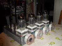
I have run the amp for 5 or 6 hours now and I am keeping the bias to around 100ma at lowish volume..
WOW!
I have been listening to and playing with audio for almost 50 years and this is the best sounding amp I have ever owned.
I have Monitor Audio Silver 6s speakers , I bought them for their overall smooth sound, but.. they have always suffered from a slightly indistinct "woolly" bass sound.... not any more, even at moderate volume the bass is distinct and clear!
the sound stage is also more distinct its like listening on headphones , the voices seem so real.
I intend to run in at low bias for several more hours before turning it up any more but I cant wait to hear it loud,
perhaps I should finish the enclosure first (so that I don't electrocute my family or myself)
See picure.
Tony.
Had a brainwave today while driving home from work!
I have spare a 500va multi tap auto transformer in my spares stash,
this is tapped at 0 - 100 - 110 - 115 - 220 - 240
I can use this to create a centre tap on my isolating transformer.
As the mains voltage in my area is reading 250v, I have fed in to the 0 - 240 tap from the isolating transformer and then used 0 - 100 -200
(effectively giving me 105 -0 -105) the centre tap is feeding through a 680 ohm resistor, as this is the closest w/w in my box to 1k.
This has stabilised the + and - rails to within 10 volts with the DC of-sett at 0.2mV per channel
this is giving me a total ht of 285v before it was about 340 Volts (too high?)
I tried shorting the centre tap to ground directly and this of course split the ht dead centre but it produced an audible hum (maybe because it effected the off-set) but I didn't leave it on for long enough to do any other tests
I have run the amp for 5 or 6 hours now and I am keeping the bias to around 100ma at lowish volume..
WOW!
I have been listening to and playing with audio for almost 50 years and this is the best sounding amp I have ever owned.
I have Monitor Audio Silver 6s speakers , I bought them for their overall smooth sound, but.. they have always suffered from a slightly indistinct "woolly" bass sound.... not any more, even at moderate volume the bass is distinct and clear!
the sound stage is also more distinct its like listening on headphones , the voices seem so real.
I intend to run in at low bias for several more hours before turning it up any more but I cant wait to hear it loud,
perhaps I should finish the enclosure first (so that I don't electrocute my family or myself)
See picure.
Tony.
Attachments
Hi,
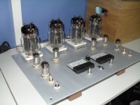
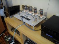
The wall is 7" away from the tubes and is only just a bit warm, as for ventilation here is a picture of the mock up of my design.
The chassis plate is quite cool thanks to the stand off's on the tube bases plus there is only 1 transformer underneath(20va for the driver tube heaters).
I may add fans below to cool the tube bases, I will see how hot it gets when finished.
Tony.
Attachments
Hi,
The wall is 7" away from the tubes and is only just a bit warm, as for ventilation here is a picture of the mock up of my design.
The chassis plate is quite cool thanks to the stand off's on the tube bases plus there is only 1 transformer underneath(20va for the driver tube heaters).
I may add fans below to cool the tube bases, I will see how hot it gets when finished.
Tony.
Interesting,
Use of the strip to create the structure..Very inventive
Its a shame you can't enclose the Tx's at the back. I guess you could use a structure mounted again on the all thread at each side..
I guess it should be Ok without the fans there is plenty of cooling with the "finned" enclosure.
Looking forward to the pics of the completed unit..
I must admit I have to fight the temptation to put a few bits on the tubes and create Daleks.LOL
Regards
M. Gregg
Last edited:
Like M.Gregg said, that chassis is a great idea!!!
I'm planning one of these too.. Was even thinking parallel output tubes, but seeing all those transformers on the back for the filaments has brought me back to reality..... I'll stick w/ 4 6c33
Now stick some dalek eye's on the tubes and call it Davros.
I'm planning one of these too.. Was even thinking parallel output tubes, but seeing all those transformers on the back for the filaments has brought me back to reality..... I'll stick w/ 4 6c33
Now stick some dalek eye's on the tubes and call it Davros.
- Home
- Amplifiers
- Tubes / Valves
- New Tim Mellows OTL project