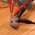
Get a socket (or use clip leads) and place a 100 or 200 ohm resistor in series with the collector. Connect a variable supply + to the resistor and - to the emitter with no connection to the base. Increase the voltage until athe collector to emitter voltage suddenly drops (avalanche). Kill the supply so as not to overheat the transisitor (THEY GET HOT!). Mark the transistor with a felt tip pen, repete for all parts present and sort by breakdown voltage.
i was given about a dozen unmarked power trannies and did that breakdown test that you mentioned.....
after frying half of them, i stopped and just used those trannies like regular 2n3055's.
So, should we not be looking at the maximum voltage a transistor in the Off State can sustain before it goes zap instead of using Vceo as the limit?
that is the same thing, Vceo is the collector emitter voltage without base input,(cut-off)....
Tony, The spec I found for 2N3055 specified 200mA for Vceo(sustaining). I misinterpreted this spec as something the transistor could sustain. It is not, but won’t damage a TO-3 2N3055 for a short while.
Other transistors will have different specifications.
If you do not know what the transistor is, start with a more conservative limit.
(Increase the resistor value to 1K and you will limit the current to 100mA at a 100V supply. I tried 10K and it limited the current too much and the MJE3055 wouldn't avalache.)
As wg_ski suggested, a current source with high voltage supply would work better but either way you have to ramp the voltage and watch the voltage as you increase it to see where avalanche takes place. Once it happens Vce drops to a lower level as current shoots up.
The issue I had was when I tried testing the 2N3055 at the same current levels as I used on the VP0106 (10s of uAs), I could not see breakdown. Apparently it takes more current for a Bipolar part. 10 mA is too little for the 2N3055 parts I tested, as it is for On Semi T2055. In some cases I see them pull up to 15mA before breakdown.
I just tested 11 Motorola MJE3055s (late 70s or early 80s, date code 013) and all of them passed 200V before breakdown. I also tested two unknown mfg MJE3055s and they passed 200V as well. The MJE3055s only pulled 20uA at 200V.
Last edited:
TheGimp, i am fully aware of what you are saying, it is just that newbies should learn it the right way, repsect the specs....
now as they grow more in experience, they can do this screening....
as for me, with todays available trannie choices, i will go for those tried and tested designs using the right trannies...
the 2n3055 here in manila costs like U$0.35 a piece, yet i will go out and spend more if only i can have the peace of mind that my builds can withstand the rail voltages they are used in.....
that is the same thing, Vceo is the collector emitter voltage without base input,(cut-off)....
") Silly me.
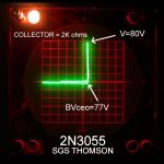
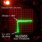
Silly me.Time to fire up the old lady, my faithful Tek 575. Just happen to have 7 pairs of 2N3055 and MJ2955 by SGS Thomson.
Best to stick to the datasheet. +/-30V rails are about max.
Attachments
Tony, I understand.
Michael, If you derate your measurement by 25% for temp rise, you end up near 61V breakdown which is about what I would expect for the device.
The sample I measured is obviously an anomaly.
If you go back to Tacuchi, Juran, Deming, etc, you will find what I was doing is not statistically valid.
Too small a sample size.
I just found it interesting that the ones I tested had such a high breakdown, which shows that some devices could function at the voltages proposed without failure.
There's nothing wrong with your measurements. The important point that we have shown is, without making any measurements, staying within the manufacturers' specs is the best approach.
If one wants to operate the 2N3055/MJ2955 at voltages beyond Vceo (60V) without making sure whether the transistors can withstand it, then one is taking the risk.
If one wants to operate the 2N3055/MJ2955 at voltages beyond Vceo (60V) without making sure whether the transistors can withstand it, then one is taking the risk.
RCA spec'd the 2N3055 at Vceo = 60V but Vcer = 70V where
Vcer is with 100 ohms from base to emitter as is seen in most
EF and Quasi output stages. I suspect the typical part will
take a bit more since they needed some statistical margin.
Again you are rolling the dice if you do not pretest.
Vcer is with 100 ohms from base to emitter as is seen in most
EF and Quasi output stages. I suspect the typical part will
take a bit more since they needed some statistical margin.
Again you are rolling the dice if you do not pretest.
RCA spec'd the 2N3055 at Vceo = 60V but Vcer = 70V where
Vcer is with 100 ohms from base to emitter as is seen in most
EF and Quasi output stages. I suspect the typical part will
take a bit more since they needed some statistical margin.
Again you are rolling the dice if you do not pretest.
do you have RCA databooks like that one from post #33 and #34 about
http://www.diyaudio.com/forums/parts/167680-vintage-transistors-4.html ??
This datasheets you will not find online, e. g. about "alldatasheet" or "datasheetarchive".
The 2N3055 datasheets from RCA are much more detailed, especially from the first years, where the 2N3055 was introduced on the market.
Last edited:
HI all
I've measured several ON Semi and ST epitaxial 2N3055's and routinely measure > 80V BVceo.
Originally RCA specified Vceo =60; Vcer (Rbe=100) =70V and BVcbo=100.
Manufacturers selling 2N3055's presumably had to meet the 100V BVcbo specification. I suspect (no proof) that because the epitaxial process had more abrupt junctions than the old hometaxial types from RCA, they had to basically manufacture a 100V transistor to meet the BVcbo spec. but then as a result got good BVcbo's well over 60V. Many epitaxial transistors often had the same BVcbo and BVceo specifications.
Generally, it seems that modern 2N3055's can be used to replace older devices at up to 80V but it is still worth checking your particular devices.
John
Thats the one.... and yes I reckon it was RMS not peak.
I noticed that the power rails are 44V there so maybe that is under full load? The maplin article says you should measure 50 to 55V!
I am pretty sure it was 45 volt rails on the one I built.
Maplin did a later version with the output transistors on a pcb/heatsink to save on wiring, perhaps that one was 55volts ?
- Status
- This old topic is closed. If you want to reopen this topic, contact a moderator using the "Report Post" button.
- Home
- Amplifiers
- Solid State
- 2n3055 amp claims 200 to 220 watt