Mats, its just down to your aspirations VS investing in time and parts. The law of diminishing returns rears its ugly head at a point. All the difference is at what point you are content. A prudent way is to go step by step and try to stop when differences start to seem like too much complication for nothing to you.
I understand your point. I was also thinking about if I actually win anything on doing supplies for each channel separately. I think I'll make the pcbs and test, if the cooling on the powersupply box is sufficent and the xformers keep cool I'll do 6 shunts and if not I'll use one per voltage. Either way, thanks for your time!
Best regards,
Mats
First I tried it out with a CRCRC+317 to get some kind of a feel, sound was good but there was too much noise
Just to be fair to the 317, which I have used very often with very good results:
1) Have you bypassed the adjust leg (100uF to 220uF)?
2) Have you used a not so low-ESR cap at the output, no larger than 220uF?
3) Have you loaded the output with a 100 ohm resistor?
The first one will improve impedance and improve noise (look for Walt Jung comparison measurements on his super-regulator articles).
The second will prevent oscillations for low-ESR caps and/or large caps, and lower noise.
The third seems to improve things all around.
Then I think comparisons can be made, considering parts quantity is quite small on a 3X7 project.
I am building some 1,2V Disco-versions (post 1616) for DAC:Avoid Schottky diodes in the Vref (1A to go 0.6V)...
1) Is there any better version than in post 1616?
2) I wonderd if there was any possible substitute to a resistor/pot (above the CCS Q5). It could be a diode with low Vf like Schottky - but is that a bad idea? If yes - can you get any (low noise) lower Vf than an ordinary silicium diode like 1N4004 of 0,6V ??
3) Christel in his noise-measurements in
http://www.diyaudio.com/forums/parts/35821-some-noise-measurements-leds-zener-diodes.html
and
http://www.diyaudio.com/forums/attachment.php?postid=417008&stamp=1087235682
meantioned a "BC549 BE diode forward biased transistor" (as even more quiet than LED). Does anyone have a schematic how that connection is done?
Peter
Last edited:
Just to be fair to the 317, which I have used very often with very good results:
1) Have you bypassed the adjust leg (100uF to 220uF)?
2) Have you used a not so low-ESR cap at the output, no larger than 220uF?
3) Have you loaded the output with a 100 ohm resistor?
The first one will improve impedance and improve noise (look for Walt Jung comparison measurements on his super-regulator articles).
The second will prevent oscillations for low-ESR caps and/or large caps, and lower noise.
The third seems to improve things all around.
Then I think comparisons can be made, considering parts quantity is quite small on a 3X7 project.
Thanks for the suggestions! I had not done 1 and 3 and for the 2nd one I only had some 10uF at home.
Just now I tested with 220uF bypass and 170R load in addition to the 3pcs10uF but I did not notice any improvement. I have to admit that my testing abilities are not more than my hearing as i do not own an oscilloscope. This means I tested and compared the shunt/317 and the suggestions driving phono stage with the preamp at full blast after and there was a big difference.
I do not mean to say anything bad about the 317, it most certanly has its applications, but comparing the noise this way the 1.2R sounds a lot better (less).
I am building some 1,2V Disco-versions (post 1616) for DAC.......
Peter
1. No
2. Use a normal diode 1N4003 or ''dioded'' BJT.
3. Andrew replied.
Mats:
You did not show your MM phono in its thread yet, yes? Take some pics and show there if you may, a few make MM version, maybe they wanna know details.
I could try take some pics later this evening of the nice breadboard I have. I started drawing some schematics in eagle last night to prepare for some PCB layout but it will probably be some weeks before I get all the parts, not ordered yet for the shunts, and the PCBs made.
Hi Salas and all,
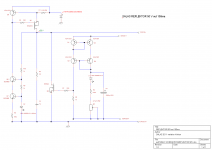
Here is a schematic for Reflektor 50V out/150ma as suggested by Salas in post #4727.
Could you check for errors please?
I finally settled on BC546B for ccs cascode ring. Not sure about R8,R9,R10 in the attached schematic.
I miss snuber across C2 as you did that on last layout suggestion.
Regards.
Here is a schematic for Reflektor 50V out/150ma as suggested by Salas in post #4727.
Could you check for errors please?
I finally settled on BC546B for ccs cascode ring. Not sure about R8,R9,R10 in the attached schematic.
I miss snuber across C2 as you did that on last layout suggestion.
Regards.
Attachments
Use a base stopper 100-120R for Q5, give same value to R2,R7. R10 maybe will need to get tied directly to +InV if you will get start-up problems by referencing to output as you have it now. See to have correct dissipation parts for R9, R10. Also R1 looks enough for 100mA only. Use at least 100mA spare over your top load demand.
")
Also R1 looks enough for 100mA only. Use at least 100mA spare over your top load demand.
Ok, there is something i don't catch with that one as it is not the first time you say that to me: calculation is Q5vbe/R1 right?
In KSA1381 datasheet it's specified as 1v vbe. What i am missing there?
EDIT: got it! It's vbe SAT which is specified! VBE still in 0,65/0,67 ballpark as for any silicon transistor.
Last edited:
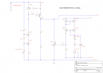
Ok. So it should look like the schematic attached.
It's a pleasure learning with you as a teacher Salas.
Could you explain me math involved with R10, R9 please. I don't get it.
For previous value of 1k i refered to wikipedia page about current source and supposed that 50V minus 2,1v (D2) divided by 2 (because of cascode), and about 2ma as target. Where am i doing it wrong?
Regards.
PS: about 70V at input, do you think i should put emphasis on prefiltering as cascode ring is referenced directly at it? I was initially thinking about C only as prefilter, maybe a CRC could be better ( i should have a little bit more than 70V on input -maybe 75v)?
Attachments
- Status
- This old topic is closed. If you want to reopen this topic, contact a moderator using the "Report Post" button.
- Home
- Amplifiers
- Power Supplies
- The simplistic Salas low voltage shunt regulator