Hi,
Maybe not. The level of common electronics in East Germany (not cutting edge mil spec stuff) was at least 10 Years if not more behind the west. I also worked with the 723 in some rather special designs.
It is noteworthy in that it can be compensated to be inherently stable (that it puts to rest arguments of "regulators need a cap across the output to be stable") and that the reference can be filtered externally...
I see the TI application note dated 1972 (revised in 1999) also shows a Shunt Regulator. Maybe a Shunt regulator is nowhere near as exotic a circuit as Sy wants to make everyone believe...?
Ciao T
You must be older than me - as a schoolboy I was building power supplies based on uA723.
Maybe not. The level of common electronics in East Germany (not cutting edge mil spec stuff) was at least 10 Years if not more behind the west. I also worked with the 723 in some rather special designs.
It is noteworthy in that it can be compensated to be inherently stable (that it puts to rest arguments of "regulators need a cap across the output to be stable") and that the reference can be filtered externally...
I see the TI application note dated 1972 (revised in 1999) also shows a Shunt Regulator. Maybe a Shunt regulator is nowhere near as exotic a circuit as Sy wants to make everyone believe...?
Ciao T
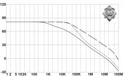
To expand a little on the earlier discussion, I just got the attached for an upcoming article for Linear Audio Vol 3.
The long-dashed line to the right is the open loop response of a regulator. You can see that it crosses the 0dB line rather steep, at a 24dB/oct rate. Such a steep angle carries with it a large phase shift, so you get in a situation with 180 degrees phase shift and still some gain > oscillations!
The solid line to the left is with a cap at the output. No more oscillations and instability because that curve crosses the 0dB line less steep, and carries less phaseshift. BUT, the gain rolls off much earlier so that means that for higher frequencies there is much less loop gain which means the regulator doesn't perform as well as it could.
Therefore the author used the small dashed line: no oscillations because the 0dB crossing is not too steep, but still using almost all the available loop gain.
Such are the deliberations of a designer...")
jan
The long-dashed line to the right is the open loop response of a regulator. You can see that it crosses the 0dB line rather steep, at a 24dB/oct rate. Such a steep angle carries with it a large phase shift, so you get in a situation with 180 degrees phase shift and still some gain > oscillations!
The solid line to the left is with a cap at the output. No more oscillations and instability because that curve crosses the 0dB line less steep, and carries less phaseshift. BUT, the gain rolls off much earlier so that means that for higher frequencies there is much less loop gain which means the regulator doesn't perform as well as it could.
Therefore the author used the small dashed line: no oscillations because the 0dB crossing is not too steep, but still using almost all the available loop gain.
Such are the deliberations of a designer...
jan
Attachments
I think the 723 and an LM317 are very different products. One is a very flexible set of regulator building blocks, with a half decent 6.9V reference, opamp and pass transistor, and he other is a high volume 3 pin workhorse device (maybe the most successful linear reg ever?).
Great example janneman - this exactly what the data sheet says and whaddaya know? It works!
Great example janneman - this exactly what the data sheet says and whaddaya know? It works!
BTW - Below, is a link to a PDF on the basics of supply passive bypassing & decoupling. One oversight is the lack of discussion regarding the unique self-damping aspect of ferrite inductors. Still, a nice introduction for beginners, and review for the more experienced.
http://www.designers-guide.org/Design/bypassing.pdf
http://www.designers-guide.org/Design/bypassing.pdf
BTW - Below, is a link to a PDF on the basics of supply passive bypassing & decoupling. One oversight is the lack of discussion regarding the unique self-damping aspect of ferrite inductors. Still, a nice introduction for beginners, and review for the more experienced.
http://www.designers-guide.org/Design/bypassing.pdf
Thanks Ken, quite worthwhile.
If you want to read about how capacitors really behave in such circumstances, see Kendall Castor-Perry's 6-part (I know....) article here:
http://www.linearaudio.nl/library misc.htm
(Its on the right side, just a bit below the middle).
jan
Thanks Ken, quite worthwhile.
If you want to read about how capacitors really behave in such circumstances, see Kendall Castor-Perry's 6-part (I know....) article here:
http://www.linearaudio.nl/library misc.htm
(Its on the right side, just a bit below the middle).
jan
Jan,
Thanks for the link to that reference list.
Jan, the key is to look now at the regulator's TRANSIENT RESPONSE with the modified equalization. Is it as good as the nominal 6dB/octave? If so, then it is OK.
As we talk around the subject of voltage regulators, finally some important aspects come forth.
First, as there must ALWAYS be a dominant pole, why not try to put it at the output, because invariably there is going to be cap loading at some point, even if it is the load itself?
Second, since one is decided upon, try to keep the other 'poles' as high and hopefully separated as possible, in order to get the most effective bandwidth and performance.
Third, it is impossible to do this wideband, effectively, IF the gain-bandwidth of the components that make up the regulator are low, and this is the cheapest practical way to make IC's.
Four, perhaps we should not expect too much above hum-ripple frequencies from these cheap regulators, as they will NOT operate beyond 1MHz.
Depends how good you want to look.
The LT1575 has an open loop gain flat to 30kHz (I knew you would be drooling now ) and can be turned into an ultra-fast regulator.
Developed for things like Pentium processors, but just don't tell them they're going to work for audio.
The problem with this type of chips is mainly to get an insight in all the issues involved, and the surrounding circuitry.
Probably not worthwhile for audio, but for really demanding applications, they are available.
jan
The LT1575 has an open loop gain flat to 30kHz (I knew you would be drooling now
) and can be turned into an ultra-fast regulator.Developed for things like Pentium processors, but just don't tell them they're going to work for audio.
The problem with this type of chips is mainly to get an insight in all the issues involved, and the surrounding circuitry.
Probably not worthwhile for audio, but for really demanding applications, they are available.
jan
OF COURSE, and please note the MAXIMUM input voltage for this regulator. They CHANGED THE PROCESS! Still, try to get that sort of performance for a +/- 30V regulator!
Perhaps there is something new, out there, and cheap enough. I will switch over to it, instantly, if it is practical to do so.
Perhaps there is something new, out there, and cheap enough. I will switch over to it, instantly, if it is practical to do so.
Hi,
I find I can make a 317 look very good under transient load and sound reasonable.
The key is a very large value electrolytic cap (a few mOhm impedance at 1KHz), plus of course the "magic" capacitor to set the chip to unity gain at AC, which also needs to be MUCH larger value than the datasheet suggests.
It also helps "pre-loading" the regulator with 100mA or more, it is easily done using the voltage set resistive divider, of course, that means we need even more capacitance for the AC bypass in the resistive divider.
The combination has flat resistive Z up to where the output cap let's go, which tends to be a few 10's KHz for something suitable.
Of course, it is brute force, totally artless, the equivalent of Operation Arc Light. But it actually works surprisingly well. But much better is possible even sticking to IC's, so I don't use this very often nowadays.
I was quite impressed with the results in the mid-90's though, I used this extensively in modifications of gear, where a pair of compact low Z-Cap's replacing what was already there and higher power resistors usually where easy to bodge in.
In a clean sheet design I would not normally resort to such methods, finesse almost always gets you better results.
Ciao T
Depends how good you want to look.
I find I can make a 317 look very good under transient load and sound reasonable.
The key is a very large value electrolytic cap (a few mOhm impedance at 1KHz), plus of course the "magic" capacitor to set the chip to unity gain at AC, which also needs to be MUCH larger value than the datasheet suggests.
It also helps "pre-loading" the regulator with 100mA or more, it is easily done using the voltage set resistive divider, of course, that means we need even more capacitance for the AC bypass in the resistive divider.
The combination has flat resistive Z up to where the output cap let's go, which tends to be a few 10's KHz for something suitable.
Of course, it is brute force, totally artless, the equivalent of Operation Arc Light. But it actually works surprisingly well. But much better is possible even sticking to IC's, so I don't use this very often nowadays.
I was quite impressed with the results in the mid-90's though, I used this extensively in modifications of gear, where a pair of compact low Z-Cap's replacing what was already there and higher power resistors usually where easy to bodge in.
In a clean sheet design I would not normally resort to such methods, finesse almost always gets you better results.
Ciao T
Well, T, please teach SY how you do it. Me, I will stick with my approach, which is to use the 317 for what it is good for, and post regulate for lower noise and transient generation.
That's valid. I just do things differently, building in high PSR into my designs. There's more than one way to get a quiet circuit.
This link showed up today, I'm not sure how on target it will be.
Choose Your Voltage Reference: Bandgap Or FGA?
Tamara Schmitz, Contributing Editor
Tamara Schmitz compares bandgap and floating-grid-array (FGA) voltage references for analog-to-digital converter (ADC) measurements in terms of temperature coefficient, noise, and drift.
Choose Your Reference Design: Bandgap Or FGA?
Hi,
To me there are great differences between modifying existing "ordinary" commercial gear, clean-sheet designing for DIY (especially DIY by others) and clean-sheet designing commercial gear.
If I modify stuff I am always interested in the biggest improvement for the least effort and without making the piece of gear look too much like a ratsnest.
Swapping out capacitors for large value ones, adding extra supply Cap's (often soldered on at the bridge rectifier or at the diodes which I tend to change for schottky) and cutting traces to add some chokes (Pi Filter for better HF filtering) and even converting 3-Pin series regs to CCS and adding local shunts with minimal parts count are the ones I find make the biggest bang here for the least effort.
For DIY I am concious that many DIY'ers struggle with complex circuits, often neither understand them nor are able to trouble-shoot them.
So if I can throw in an inexpensive 10H Choke and a big audio grade cap for filtering the supply to a single J-Fet MC Headamp by 70dB at 100Hz and more above without self noise, I choose that over a complex discrete low noise regulator, not because I cannot do it, but because it saves me headaches to help people when they get stuck.
For commercial gear, which goes onto PCB's and is mass produced typically seriously "exotic" components are not in the budget, but I can have as many SMD SOT-23 BJT's as I want and anything else that is cheap and plentiful.
And for many essential high cost parts there is little price difference between off the shelf parts and custom designs. For example, the difference in cost between a generic 40VA EI transformer with a dual secondary and one with additional screens, extra windings and non-standard winding stackups (for better HF filtering) is notional, a few percent.
So I design in considerable complexity and use custom specified parts to get excellent performance from generic and inexpensive parts, and I push as much of secondary hardware functions into software - FPGA's, CPLD's, MCU's, PIC's etc.. Easier and cheaper to fix code than to redo the layout, solderpaste template and all for a PCB.
It is always horses for courses, with me anyway...
Ciao T
Me, I will stick with my approach, which is to use the 317 for what it is good for, and post regulate for both lower noise and transient generation. Very high frequency rejection, too!
To me there are great differences between modifying existing "ordinary" commercial gear, clean-sheet designing for DIY (especially DIY by others) and clean-sheet designing commercial gear.
If I modify stuff I am always interested in the biggest improvement for the least effort and without making the piece of gear look too much like a ratsnest.
Swapping out capacitors for large value ones, adding extra supply Cap's (often soldered on at the bridge rectifier or at the diodes which I tend to change for schottky) and cutting traces to add some chokes (Pi Filter for better HF filtering) and even converting 3-Pin series regs to CCS and adding local shunts with minimal parts count are the ones I find make the biggest bang here for the least effort.
For DIY I am concious that many DIY'ers struggle with complex circuits, often neither understand them nor are able to trouble-shoot them.
So if I can throw in an inexpensive 10H Choke and a big audio grade cap for filtering the supply to a single J-Fet MC Headamp by 70dB at 100Hz and more above without self noise, I choose that over a complex discrete low noise regulator, not because I cannot do it, but because it saves me headaches to help people when they get stuck.
For commercial gear, which goes onto PCB's and is mass produced typically seriously "exotic" components are not in the budget, but I can have as many SMD SOT-23 BJT's as I want and anything else that is cheap and plentiful.
And for many essential high cost parts there is little price difference between off the shelf parts and custom designs. For example, the difference in cost between a generic 40VA EI transformer with a dual secondary and one with additional screens, extra windings and non-standard winding stackups (for better HF filtering) is notional, a few percent.
So I design in considerable complexity and use custom specified parts to get excellent performance from generic and inexpensive parts, and I push as much of secondary hardware functions into software - FPGA's, CPLD's, MCU's, PIC's etc.. Easier and cheaper to fix code than to redo the layout, solderpaste template and all for a PCB.
It is always horses for courses, with me anyway...
Ciao T
Just in from Bdent.com
...Sanyo Semiconductor, officially closed in the United States
Ouch!!! Glad I bought several last year for my Adcom GFA-535. I better lock the extras up in a safe.
Just in from Bdent.com
...Sanyo Semiconductor, officially closed in the United States
The Sanyo semicon business was absorbed by ON Semi, last year - but many transistors appear to have been lost in the process. On top of a flooded factory in Thailand.
Before this subject is lost:
T, I congratulate you for 'thinking outside the box' and giving me both new and old concepts (some I used to do, and discarded over the years) to ponder.
However, you have not solved SY's original challenge (dilemma?) of getting adequate performance for HI END AUDIO from a LM317 directly connected to the preamp stage.
At least, this is what I remember him claiming was OK to do.
My approach is simple, but elegant. However, things have gotten out of hand, because of limitations in the availability of low noise parts and their Idss ranges. This has forced me to use many expensive, PARALLEL parts to get the specified performance that I need. It is doable, but at the cost of about 50 fets per channel. Hard to get, fets, too! Still, it is necessary in my case.
- Status
- Not open for further replies.
- Home
- Member Areas
- The Lounge
- John Curl's Blowtorch preamplifier part II