I used computer as a source, recording and FFT analysis tool.
More specific Audacity program: Audacity: Download for recording and analysis, and Windows Mediaplayer for playing 1kHz signal generated in Audacity.
So there is a chance that spectra are not so fabuluos duo to computer soundcard distortion. Nonetheless it can be used to trim amplifier.
More specific Audacity program: Audacity: Download for recording and analysis, and Windows Mediaplayer for playing 1kHz signal generated in Audacity.
So there is a chance that spectra are not so fabuluos duo to computer soundcard distortion. Nonetheless it can be used to trim amplifier.
When you run any kind of FFT or analog "narrow bandpass" scan it's useful to establish a couple of baselines -- you can short the RCA's on the input and see whether you're picking up interference from a power supply, video card etc, you can connect the test leads and terminate them in a 50R load and see how much interference is picked up by the cabling. Generally, if these unhelpful artifacts are 30% or less of the fundamental the RMS'ing works out such that you're better than 2-sigmas.

So that's the noise floor.
View attachment 262017
Try with the input shorted -- I ran this test a half-dozen times to make sure my eyes weren't fooling me -- although I believe that the numbers below 30Hz or so are bogus as they are well below the threshold of the SYS2722. This is noise referenced to 0dBV.
Bottom graph is an F5 connected to the analyzer, but not to the a.c. line, second test is connected to the power line, but not "ON", third is with the F5 on.
Attachments
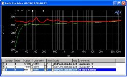
Better than -100dB ref 1Vac (0dBV)?
That's equivalent to no individual frequency giving more than 10uVac at the output.
Adding all the frequencies together would give the total noise at the output. Expect <100uVac
I am surprised there is no 3rd harmonic of the 60Hz mains.
That's equivalent to no individual frequency giving more than 10uVac at the output.
Adding all the frequencies together would give the total noise at the output. Expect <100uVac
I am surprised there is no 3rd harmonic of the 60Hz mains.
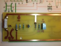
I know that official F5 amp has one source resistor 0.47 Ohm and other is 0.39 hm (0.47 + 2.4 in paralell).
I am unaware of this being the official circuit.

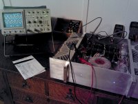
Well... Could not wait anymore for Turbo F5
I ripped one of mine F4's apart, did a new pcb, and fired it up today.
The offsett was a little jumpy at first, but when the IRF's was getting hot, it stabilised nicely... actually very near 0mV.
I had no problem, adjusting the Bias at 0,6V. So first quick test was fine, with 2K2 across trimpot's.
Next i will assamble it with heatsink compound, and try to give it a listning.
Jesper.
Attachments
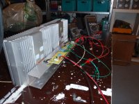

You sure do have a lot of thermal connections between the output transistors and the heat sink. Can't help but think mounting the transistors directly on the heat sink would transfer the heat better (I see the copper pad, but still). Use a piece of the U bracket to mount the F5 board at 90 degrees.
Secondly, looks like my wife's dining room table during my last amp build. Hope you can get the paint and thermal compound off before she gets home!
Secondly, looks like my wife's dining room table during my last amp build. Hope you can get the paint and thermal compound off before she gets home!
At least he's at the dinner table, my F5 testing is relegated to the buffet
Nice Tiger Oak!
- Home
- Amplifiers
- Pass Labs
- F5 power amplifier