paper will be a source of fuel for burning.
Similarly most varnishes will be fuel for burning.
Adhesives will be a fuel for burning.
Asbestos and glasswool and rockwool and mica have a very high resistance to burning. (I am not suggesting you use any of these, just showing what the difference is when thinking of Fuel).
You must choose carefully to avoid combustion during/after overheating.
BTW,
combustion (or charring) results in carbon residue that is likely to conduct electricity.
Hi temperature Mylar tape (without adhesive) is often used, but difficult to source.
Last edited:
Have a look at this page, it has some good info on winding your own transformers, including info about insulating material.
output-trans-winding.html
output-trans-winding.html
the pressure inside a multilayer winding can be huge - each additional layer of wire's winding tension adds to the pressure
then there is also extreme stress concentration when wires cross at angles instead of laying in the layers evenly
teflon in particular embodies the concept of "plastic" to a unintuitive extreme - the molecules are so slippery they will slide past each other on a very long time scale - look up "creep" in plastics
our intuition is more experienced with stuff like mylar that "work hardens" as stretching orients the molecules along the stress axis and they stick together enough to become more resistant to further deformation
teflon basicaly creeps forever
Last edited:
ok, I wil to try find nomex ")
but if I can't find maybe I will use plumber's teflon tape I have it a lot
I don't know if anyone has really use it before on trafo making, maybe I'll be the one
the point is I must use anything that can resist fire & thin enough to put in
Thanks to all reply
but if I can't find maybe I will use plumber's teflon tape I have it a lot
I don't know if anyone has really use it before on trafo making, maybe I'll be the one
the point is I must use anything that can resist fire & thin enough to put in
Thanks to all reply
Last edited:
Thanks Tonyi use all of these in my transformer builds....
i use "fishpaper", kraft paper, and many other kinds of papers, i never had a traffo burn out on me......
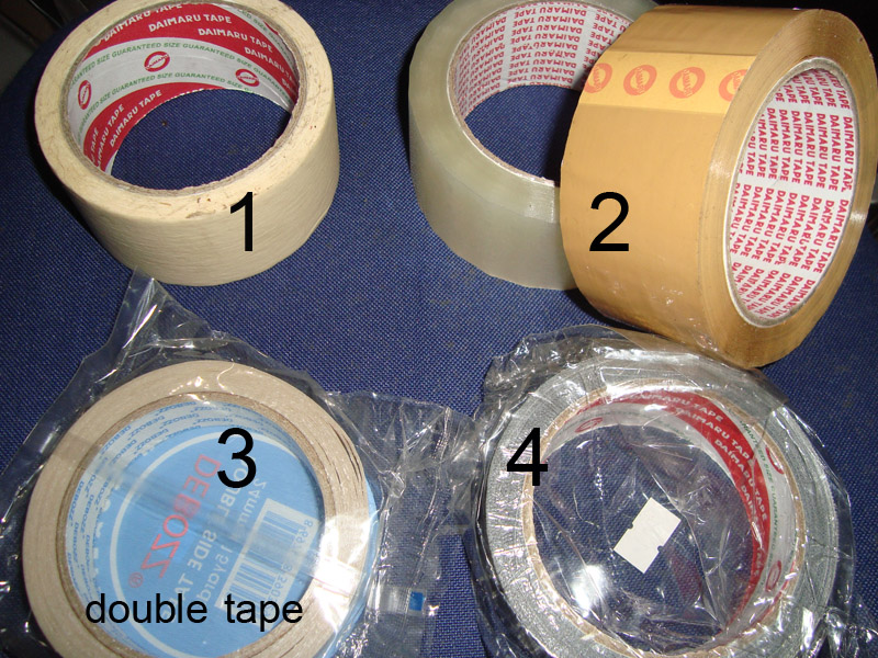
I find this paper
Maybe it is can be used...
my mother often use it in the kitchen to make some cake
btw, now is mother's day here in my country
Happy mother's day for my mom
wish you all the best
Then if we make trafo that run cool (below 1T)
why we need so expensive insulator material?
But if we run the trafo more than 1T
that good insulating material must be used
So if I go 0.8-0.9T & I use this paper I guess it just okay
but if not okay please tell me...
The trafo that I made earlier even not using inter layer insulator
Attachments

Last edited:
The Power transformer we are going to compute specifies 12 volts output with 750ma current (my Example) converting milliamperes to ampere will give us. .75a , multiplying voltage by current gives us wattage or power.
12x.75 = 9 watts
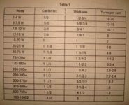
after having solved for the wattage of the transformer, which is 9 watts, look at Tables 1, where 9 watts is listed, follow the table horizontally and pick up the date for the center leg, thickness and turns per volt.
Center leg - 3/4
thickness - 3/4
turns per volt - 10
the nest step is to compute for the number of turns for the the primary and secondary coils respectively. the number of turns per volts in the primary is equal to the number of turns per volts in the secondary.
Primary coil - 220 volt (base our voltage rating in our country which is the PHILIPPINES)
Secondary coil - 12 volts
Number of turns (primary) = 220x10 = 2200 turns
Number of turns (secondary) = 12x10 = 120 turns
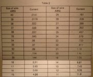
having computed for the number of turns in the primary and secondary coils. determine the sizes of wire for these coils in the next step . before computing for the guage or size of wire (AWG) must find out the current capacities of wires and their corresponding sizes. this data is provided in table 2 .
the power formula is used again in solving for the currents of wires in the primary and secondary. dividing the watts over voltage gives us the current of the wire:
I = w/e
I secondary = 9watts/12volts = .75 a
I primary = 9watts/220volts = .04a
after having solved for the currents of wires pick up the corresponding sizes of wires from table 2. choose the closest current listed in the table.
Size of wires (Primary) - #35
Size of wires (Secondary) - #23
in case of a multi-voltage secondary, the higher voltage should be taken for computation. if the transformer has multiple secondary coils, the wattage of each coil is computed and then summed up. in other words, the wattage of the primary is equal to the total wattage of all secondary coils.
if the secondary coil is only center-taped, half of the wattage and current is taken to compute for the wattage of that coil.
the primary is 220-0 volts, the secondary is 12-0-12 volts
12x.75 = 9 watts
after having solved for the wattage of the transformer, which is 9 watts, look at Tables 1, where 9 watts is listed, follow the table horizontally and pick up the date for the center leg, thickness and turns per volt.
Center leg - 3/4
thickness - 3/4
turns per volt - 10
the nest step is to compute for the number of turns for the the primary and secondary coils respectively. the number of turns per volts in the primary is equal to the number of turns per volts in the secondary.
Primary coil - 220 volt (base our voltage rating in our country which is the PHILIPPINES)
Secondary coil - 12 volts
Number of turns (primary) = 220x10 = 2200 turns
Number of turns (secondary) = 12x10 = 120 turns
having computed for the number of turns in the primary and secondary coils. determine the sizes of wire for these coils in the next step . before computing for the guage or size of wire (AWG) must find out the current capacities of wires and their corresponding sizes. this data is provided in table 2 .
the power formula is used again in solving for the currents of wires in the primary and secondary. dividing the watts over voltage gives us the current of the wire:
I = w/e
I secondary = 9watts/12volts = .75 a
I primary = 9watts/220volts = .04a
after having solved for the currents of wires pick up the corresponding sizes of wires from table 2. choose the closest current listed in the table.
Size of wires (Primary) - #35
Size of wires (Secondary) - #23
in case of a multi-voltage secondary, the higher voltage should be taken for computation. if the transformer has multiple secondary coils, the wattage of each coil is computed and then summed up. in other words, the wattage of the primary is equal to the total wattage of all secondary coils.
if the secondary coil is only center-taped, half of the wattage and current is taken to compute for the wattage of that coil.
the primary is 220-0 volts, the secondary is 12-0-12 volts
Attachments
Thanks tranqspogi, its useful for me...the primary is 220-0 volts, the secondary is 12-0-12 volts
our primary is the same that is good but I guess the frequency is different.
Right here in Indonesia that is 50Hz, so my trafo need more turn for same T.
Btw I want some opinion about the "red paper" that I attach,
I want to use it, or maybe you can tell me what paper did you use to make your transformer? or some picture of it
Regards
Thank you tranqspogi for the great information and excellent examples.
But I would like to know where I might be able to access the tables that you have pictures of??? I am sure the internet has them somewhere, but it would be bennificial if you could direct some of us laymen to the proper website.
Thank you for your knowlege.
But I would like to know where I might be able to access the tables that you have pictures of??? I am sure the internet has them somewhere, but it would be bennificial if you could direct some of us laymen to the proper website.
Thank you for your knowlege.
Thanks Tony
I find this paper
Maybe it is can be used...
my mother often use it in the kitchen to make some cake
btw, now is mother's day here in my country
Happy mother's day for my mom
wish you all the best
Then if we make trafo that run cool (below 1T)
why we need so expensive insulator material?
But if we run the trafo more than 1T
that good insulating material must be used
So if I go 0.8-0.9T & I use this paper I guess it just okay
but if not okay please tell me...
The trafo that I made earlier even not using inter layer insulator
you can use that paper.....make sure it is dry.....
salam kenal....saya arif dr jkt,Does someone know the formula
to get the best numbers of turn to this kind of transformer/trafo?
I do have the formula, but maybe some other formula to compare with
This my formula for EI trafo for 50 Hertz frequency
primary winding
n = 45 * V / A
secondary winding
n = 49.5 * V / A
n = number of winding turn
V = voltage input or output (volt)
A = core area (cm square)
Maybe someone help to add another formula here, please...
Wanted, trafo DIYers
Thanks
bli Nyoman pnya skema smps 500w ga?
tentunya sparepartnya yg mudah dicari di jkt.
 Riff This is an English speaking forum. Please post an English translation with your post.
 Hi Andrew the only part that was translated from English was "Please Post an English translation with your post" I find that the translation engines work best with simple sentences
The translation engine did not do a particularly good job of translating the post I referred to though, so whether my message gets through I am uncertain, but putting the Indonesian back through (always a good test) returns "Please post the English translation" So I guess google simplified it
Tony.
The translation engine did not do a particularly good job of translating the post I referred to though, so whether my message gets through I am uncertain, but putting the Indonesian back through (always a good test) returns "Please post the English translation" So I guess google simplified it
Tony.
This question has been asked many times and answered almost as many times.
During my HND training we were taught the following formula.
Turns/Volt = (1 x 10e9) / (K * FF * B * f * Ai)
Where FF is Form Factor - 1.11 for Sine Wave, 1.00 for Square Wave and 1.10 for Triangular Wave.
K = 4
B = Max Flux Density in mT. (780mT is good practice but anything up to 1350mT)
Ai = Area of magnetic CORE in square millimeters
f = Frequency
And for Ai:
Ai = (Square Root W) / K
Where W is 110% of the TOTAL secondary power
K = 0.0086 for EI, 0.015 for TU and 0.035 for Ferrite type A13
- Status
- This old topic is closed. If you want to reopen this topic, contact a moderator using the "Report Post" button.
- Home
- Amplifiers
- Power Supplies
- Iron Core Transformer Formula