Something that is sometimes desirable is a method for determining the relative acoustic offset of two drivers in a multi-way system, and most of the methods I've seen that are open to a DIY'er aren't that accurate or easy to do.
One approach that is sometimes suggested for even order crossovers is to simply reverse the phase of one driver (from its normal phase) and look for a notch in the response - as the tweeter is moved forward or back a deep notch will be found at the correct point.
The problem with this is that you are not really determining the time alignment of the drivers but rather phase tracking through the overlap region, which is not the same thing.
If the acoustic low pass and high pass transfer functions (filter+driver response) are perfectly aligned to their theoretical ideal (for example L/R 2nd or 4th order) then the notch will occur when the drivers are time aligned, but for any other situation it will not.
Many (most?) designs deliberately choose not to time align the drivers for practical reasons and simply bend the filter response(s) to ensure close phase tracking, in this case you have phase tracking but not time alignment, and no easy way to determine what driver offset would have given time alignment if you had so desired it.
A better approach is to measure the impulse response of each driver independently and compare the arrival time differences at a microphone whose height is equidistant between the centre of each driver. By comparing arrival times in fractions of a millisecond a distance offset can be calculated.
Many software measurement systems such as ARTA can do this, however there are some significant practical challenges to accurately measuring this way:
1) It requires a way to measure each driver independently. If its your own design this isn't a big deal - disconnect one driver and substitute a load resistor and vica-versa. If you want to measure a fully assembled speaker without dismantling it, you're out of luck however.
2) It's the beginning of the impulse rise of each driver that must be determined, not the peak. This is not too difficult for a tweeter with its sharp impulse rise, but a low pass filtered woofer will have a very slow impulse rise, making determining exactly where it begins to rise very inaccurate. You could easily be out by several samples.
Disconnecting the low pass filter and running the woofer direct is one option, but depending on the woofer the rise time may still be quite slow, and again it involves messing with the crossover.
3) Significant error due to the sample step size - even if you were somehow able to accurately judge where the woofers impulse begins to rise, you still have to select a discrete sample. At 48Khz 1 sample is ~21usec, which corresponds to an acoustic propagation distance of ~7mm.
This means that the +/- 1 sample uncertainty introduces a minimum error of +/- 7mm per driver, if the error for each driver stacks there is potentially an error of up to 14mm simply due to the sample time period and the inherent +/- 1 uncertainty. This compounds on top of the difficulty of establishing where the woofers impulse begins to rise. 96Khz sampling rate will halve the potential error, but it's still an issue.
4) Accurate time comparisons of two separately taken measurements on a PC is very difficult. To be really certain that both separate measurements are accurate to the same sample requires a dual channel measurement technique, which some software (Holm Impulse) doesn't support. Even for software like ARTA which supports dual channel, there are significant hassles and limitations involved with using dual channel mode that make its use less than ideal.
While pondering better ways to measure relative acoustic offset and looking through some of my measurements it suddenly dawned on me that maybe excess group delay could be use as a simple and fairly accurate way to measure the acoustic centre offset of two drivers, with one single channel measurement, and without touching the crossover in any way.
Group delay is a representation of the relative propagation delay of different frequencies through a system, so if you have two drivers whose acoustic centres are physically displaced, one providing low frequencies and one high frequencies there should be some net group delay difference between high and low frequencies.
Because group delay is derived from phase, and phase changes with amplitude response, so too does group delay. This means any irregularities in the drivers frequency response (and therefore phase response) such as peaks and dips will also generate group delay - in fact typically more than the group delay caused by the physical misalignment, making it unsuitable for our purpose.
However we can also find excess group delay, which is measured group delay minus the group delay calculated from the amplitude response, by doing this we factor out all the group delay caused by changes in the amplitude response.
What's left is group delay caused by the crossover function itself (which will cause a peak near the crossover frequency) and group delay caused by the driver offsets. (Which will cause a shelf in group delay straddling either side of the peak)
Provided we have sufficient measurement bandwidth on either side of the crossover frequency, the "saddle" on either side should be a good relative indication of the relative group delay of the two drivers, thus their acoustic offset, largely independent of the type of crossover that may be employed.
A practical measurement taken in ARTA would go something like this:
1) The microphone is set to a height exactly half way between the centres of the two drivers, and at sufficient distance so that the angle to each driver is minimal. (More on this later) Lets say 1 metre.
2) A normal impulse measurement is taken and the longest reflection free period possible is windowed on the impulse with the start marker just before the impulse.
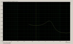
3) Enter smoothed FR view and verify that the frequency response looks good and is free of obvious ripples due to reflections. In the view menu switch to group delay and also tick Excess group delay. It's probably a good idea to tick Time-bandwidth requirement in the view menu to remind us to ignore anything below the time-bandwidth requirement of the selected window size.
You will see what looks like a nearly flat line because we need to zoom in a lot from the defaults. This is a little bit clumsy but you basically need to keep clicking on the down arrow for Range to expand the range and also the up arrow for top, to keep the line on the screen. You want a range where the entire vertical axis represents about 0.5ms.
You will now see something perhaps similar to the attached screen shot. In this example there is a 3rd order crossover at 4Khz, drivers in phase, with a tweeter that is approximately (measured by other means) 30mm too far ahead of the woofer to be time aligned. Due to the filter orders and the offset the two drivers are fairly closely phase tracking.
4) Decide where you want your time zero reference to be - if the tweeter is further forward you probably want this to be time zero, so click and drag near the right hand side until you find the "saddle" where the time value is lowest, in my example at 20Khz. (For this to be accurate 96Khz sample rate may be required)
5) With the cursor still on this point go to Edit->Delay for Phase estimation, and adjust this value until the delay reported for the cursor at the bottom left of the screen is zero - you may have to manually enter a value if the arrow increments are too large.
6) Now you have your time reference set, click and drag the cursor to the saddle in the woofers frequency range (in my example around 700Hz) and you can directly read off the time delay - in my example 0.096ms. If you multiply this by 344m/s you will get a distance, eg 0.096x10^-3 * 344 = 33.024x10^-3 = ~33mm.
This suggests that the acoustic centre of the woofer is about 33mm further back from the microphone than the tweeter. Because the line from the microphone to each driver is at a small angle, it won't be exactly the offset between the two drivers, although you could easily calculate it with a bit of trigonometry, however it will be fairly close if the measurement distance is large compared to the driver separation.
The way I see it, there are many advantages of this technique compared to trying to measure time offset to impulse start:
1) No need to open up a speaker or tamper with its crossover, just perform a single on-axis impulse based measurement with the only proviso that the necessary microphone height is accurately calculated and measured.
2) No need for dual channel measurement mode.
3) No ambiguity of trying to visually judge where a slowly rising impulse starts on a woofer, and no 20us rounding errors due to having to select a specific sample. Due to the way the excess group delay is calculated, ARTA (at least) can interpolate it to sub-sample time periods, probably down to 1us.
What I'm interested to find out, from those who have more theoretical understanding of group delay than me, is have I got this right, and what are the sources of potential error ?
I've tried a couple of different speaker and crossover combinations, and it seems to be relatively free of error due to differences in the crossover provided that there is sufficient measurement bandwidth both below and above the crossover point so that we are able to see the group delay of each driver level out.
I'm only suggesting it as a possible method for midrange to tweeter crossovers as getting a long enough window time to measure a woofer to midrange crossover seems unlikely, however accurate measurement of small acoustic offsets at low frequencies isn't really necessary.
I'm also not wanting to start a debate (in this thread at least) on whether acoustic centre alignment of drivers is important or not, (over and above phase tracking) I'm simply presenting what seems to be a very convenient and hopefully accurate way of measuring it.
Thoughts ?")
One approach that is sometimes suggested for even order crossovers is to simply reverse the phase of one driver (from its normal phase) and look for a notch in the response - as the tweeter is moved forward or back a deep notch will be found at the correct point.
The problem with this is that you are not really determining the time alignment of the drivers but rather phase tracking through the overlap region, which is not the same thing.
If the acoustic low pass and high pass transfer functions (filter+driver response) are perfectly aligned to their theoretical ideal (for example L/R 2nd or 4th order) then the notch will occur when the drivers are time aligned, but for any other situation it will not.
Many (most?) designs deliberately choose not to time align the drivers for practical reasons and simply bend the filter response(s) to ensure close phase tracking, in this case you have phase tracking but not time alignment, and no easy way to determine what driver offset would have given time alignment if you had so desired it.
A better approach is to measure the impulse response of each driver independently and compare the arrival time differences at a microphone whose height is equidistant between the centre of each driver. By comparing arrival times in fractions of a millisecond a distance offset can be calculated.
Many software measurement systems such as ARTA can do this, however there are some significant practical challenges to accurately measuring this way:
1) It requires a way to measure each driver independently. If its your own design this isn't a big deal - disconnect one driver and substitute a load resistor and vica-versa. If you want to measure a fully assembled speaker without dismantling it, you're out of luck however.
2) It's the beginning of the impulse rise of each driver that must be determined, not the peak. This is not too difficult for a tweeter with its sharp impulse rise, but a low pass filtered woofer will have a very slow impulse rise, making determining exactly where it begins to rise very inaccurate. You could easily be out by several samples.
Disconnecting the low pass filter and running the woofer direct is one option, but depending on the woofer the rise time may still be quite slow, and again it involves messing with the crossover.
3) Significant error due to the sample step size - even if you were somehow able to accurately judge where the woofers impulse begins to rise, you still have to select a discrete sample. At 48Khz 1 sample is ~21usec, which corresponds to an acoustic propagation distance of ~7mm.
This means that the +/- 1 sample uncertainty introduces a minimum error of +/- 7mm per driver, if the error for each driver stacks there is potentially an error of up to 14mm simply due to the sample time period and the inherent +/- 1 uncertainty. This compounds on top of the difficulty of establishing where the woofers impulse begins to rise. 96Khz sampling rate will halve the potential error, but it's still an issue.
4) Accurate time comparisons of two separately taken measurements on a PC is very difficult. To be really certain that both separate measurements are accurate to the same sample requires a dual channel measurement technique, which some software (Holm Impulse) doesn't support. Even for software like ARTA which supports dual channel, there are significant hassles and limitations involved with using dual channel mode that make its use less than ideal.
While pondering better ways to measure relative acoustic offset and looking through some of my measurements it suddenly dawned on me that maybe excess group delay could be use as a simple and fairly accurate way to measure the acoustic centre offset of two drivers, with one single channel measurement, and without touching the crossover in any way.
Group delay is a representation of the relative propagation delay of different frequencies through a system, so if you have two drivers whose acoustic centres are physically displaced, one providing low frequencies and one high frequencies there should be some net group delay difference between high and low frequencies.
Because group delay is derived from phase, and phase changes with amplitude response, so too does group delay. This means any irregularities in the drivers frequency response (and therefore phase response) such as peaks and dips will also generate group delay - in fact typically more than the group delay caused by the physical misalignment, making it unsuitable for our purpose.
However we can also find excess group delay, which is measured group delay minus the group delay calculated from the amplitude response, by doing this we factor out all the group delay caused by changes in the amplitude response.
What's left is group delay caused by the crossover function itself (which will cause a peak near the crossover frequency) and group delay caused by the driver offsets. (Which will cause a shelf in group delay straddling either side of the peak)
Provided we have sufficient measurement bandwidth on either side of the crossover frequency, the "saddle" on either side should be a good relative indication of the relative group delay of the two drivers, thus their acoustic offset, largely independent of the type of crossover that may be employed.
A practical measurement taken in ARTA would go something like this:
1) The microphone is set to a height exactly half way between the centres of the two drivers, and at sufficient distance so that the angle to each driver is minimal. (More on this later) Lets say 1 metre.
2) A normal impulse measurement is taken and the longest reflection free period possible is windowed on the impulse with the start marker just before the impulse.
3) Enter smoothed FR view and verify that the frequency response looks good and is free of obvious ripples due to reflections. In the view menu switch to group delay and also tick Excess group delay. It's probably a good idea to tick Time-bandwidth requirement in the view menu to remind us to ignore anything below the time-bandwidth requirement of the selected window size.
You will see what looks like a nearly flat line because we need to zoom in a lot from the defaults. This is a little bit clumsy but you basically need to keep clicking on the down arrow for Range to expand the range and also the up arrow for top, to keep the line on the screen. You want a range where the entire vertical axis represents about 0.5ms.
You will now see something perhaps similar to the attached screen shot. In this example there is a 3rd order crossover at 4Khz, drivers in phase, with a tweeter that is approximately (measured by other means) 30mm too far ahead of the woofer to be time aligned. Due to the filter orders and the offset the two drivers are fairly closely phase tracking.
4) Decide where you want your time zero reference to be - if the tweeter is further forward you probably want this to be time zero, so click and drag near the right hand side until you find the "saddle" where the time value is lowest, in my example at 20Khz. (For this to be accurate 96Khz sample rate may be required)
5) With the cursor still on this point go to Edit->Delay for Phase estimation, and adjust this value until the delay reported for the cursor at the bottom left of the screen is zero - you may have to manually enter a value if the arrow increments are too large.
6) Now you have your time reference set, click and drag the cursor to the saddle in the woofers frequency range (in my example around 700Hz) and you can directly read off the time delay - in my example 0.096ms. If you multiply this by 344m/s you will get a distance, eg 0.096x10^-3 * 344 = 33.024x10^-3 = ~33mm.
This suggests that the acoustic centre of the woofer is about 33mm further back from the microphone than the tweeter. Because the line from the microphone to each driver is at a small angle, it won't be exactly the offset between the two drivers, although you could easily calculate it with a bit of trigonometry, however it will be fairly close if the measurement distance is large compared to the driver separation.
The way I see it, there are many advantages of this technique compared to trying to measure time offset to impulse start:
1) No need to open up a speaker or tamper with its crossover, just perform a single on-axis impulse based measurement with the only proviso that the necessary microphone height is accurately calculated and measured.
2) No need for dual channel measurement mode.
3) No ambiguity of trying to visually judge where a slowly rising impulse starts on a woofer, and no 20us rounding errors due to having to select a specific sample. Due to the way the excess group delay is calculated, ARTA (at least) can interpolate it to sub-sample time periods, probably down to 1us.
What I'm interested to find out, from those who have more theoretical understanding of group delay than me, is have I got this right, and what are the sources of potential error ?
I've tried a couple of different speaker and crossover combinations, and it seems to be relatively free of error due to differences in the crossover provided that there is sufficient measurement bandwidth both below and above the crossover point so that we are able to see the group delay of each driver level out.
I'm only suggesting it as a possible method for midrange to tweeter crossovers as getting a long enough window time to measure a woofer to midrange crossover seems unlikely, however accurate measurement of small acoustic offsets at low frequencies isn't really necessary.
I'm also not wanting to start a debate (in this thread at least) on whether acoustic centre alignment of drivers is important or not, (over and above phase tracking) I'm simply presenting what seems to be a very convenient and hopefully accurate way of measuring it.
Thoughts ?
Attachments
Last edited:
Very nice, thanks for the ideas.
When developing my past few crossovers this is similar to, tho more sophisticated than, the approach I took. I used the "causal impulse" alignment in HOLMImpluse and then discovered the excess Group Delay on ARTA. They seem to agree with each other.
However, because of the size of my speakers (large) I put the mic about 5 feet away and on a line that went to the listening position. I used a string to find the line.
I've had a hard time getting the super tweeters aligned (if it matters) so will try your method and report back.
I can't respond to every detail of your very long letter but want to make one point.
As you know group delay and phase response are related, but if we are talking about system construction from multiple parts then the phase allignment through the crossover region is the primary concern. Group delay considerations won't guarantee this.
Two units will have the same group delay if they have the same slope of phase curve. This really needs to be viewed in a linear frequency scale rather than the usual log scale. Also, a phase curve only implies a particular delay if it is linear and tracks back to 0 degrees at 0 Hertz.
Even then two curves can have a constant phase span between them (one won't track back to 0 at 0) and they will not add in phase. for this reason I would always rely on phase curves rather than group delay curves. It shows you what you really need to know.
I have played with time allignment via impulse response and also find it unreliable. For the most part it tells you about mid band time delay for each unit, when you again only care about phase through the regions of overlap. You can time allign two units (in the middle of their bands) and still have poor phase overlap in the crossover region, leading to poor combined frequency response.
Whats wrong with just measuring phase?
David
HOLMImpulse suggests using its high and low pass filters to look at the impulse only thru the crossover region. I did this with 1 octave on either side and it seemed to work well.
I can see this working. Active subs with auto allignment (room correction systems) have the same issue and I believe some have used this approach.
Still, if you have the ability to measure phase you will directly see what matters most.
David S.
Jean-Michel seems to think so. His tweaked 3rd order filter is supposed to do better square waves. (It does, I've tested it).....are the restitution of square waves a good witness for this ?
Still, if you have the ability to measure phase you will directly see what matters most.
Most test suites do. We need to ask Simon again "what wrong with phase?" Tho I've often found it confusing, wrapped or unwrapped.
Everyone should own a copy of D'Appolito's Testing Loudspeakers.
In the book, he suggests a simple technique for measuring driver offset. The microphone is setup on the axis of one driver (usually the tweeter) and that becomes the reference driver. The we measure the impulse response and calculate the unwrapped phase response. Then calculate the minimum phase response (amplitude variation) and subtract the minimum phase response from the total to get the excess phase. This excess phase comes from the "time delay between the application of the impulse to the DUT and its arrival at the microphone." The excess phase viewed on a linear scale is a straight line, meaning it is a pure time delay. Multiply by 344 m/s and you get the distance of the driver from the microphone. Do the same for other drivers in the system and use a bit of trignometry to calculate the driver offset.
In the book, he suggests a simple technique for measuring driver offset. The microphone is setup on the axis of one driver (usually the tweeter) and that becomes the reference driver. The we measure the impulse response and calculate the unwrapped phase response. Then calculate the minimum phase response (amplitude variation) and subtract the minimum phase response from the total to get the excess phase. This excess phase comes from the "time delay between the application of the impulse to the DUT and its arrival at the microphone." The excess phase viewed on a linear scale is a straight line, meaning it is a pure time delay. Multiply by 344 m/s and you get the distance of the driver from the microphone. Do the same for other drivers in the system and use a bit of trignometry to calculate the driver offset.
I've thought about this a little more and I'm not sure that pursuing equalized group delay will ever get you to the goal of well merged sections.
If we divorce this from speakers we can think in terms of summing electrical (or transfer function) bandpasses. I assume an in-phase LR approach is desired, although quadrature approaches can also be used.
Each driver section can be thought of as a bandpass of some high and low rolloff order. A 2-way may be a 50 to 3000Hz bandpass and the tweeter may be a 3000 to 25,000 Hz bandpass. We can work with any rolloff orders and they can be unequal. The phase curve that goes along with a given bandpass will have 0 phase shift in the center and then phase shifts at the end proportional to rolloff slope (1/2 the ultimate phase shift at the corner frequency). If we start with units with no delay then there will be 0 degrees phase shift in the center of the bandpass. Low frequencies will allways phase advance and high frequencies will always phase retard. If the band pass is sufficiently wide then there will be a region of approximately flat phase in the center which represents 0 group delay, otherwise the section will have some delay throughout its range.
If either unit has inherent delay (is recessed relative to the other) then it will have additional phase rotation (down at HF) and, yes, there will probably be lots of phase rotations to make the picture confusing.
Now the act of constructing a crossover is to get the down rolling phase of the lower section and the up rolling phase of the upper section to match sufficiently well over a sufficiently broad region of overlap (say until one unit or the other is 15 to 20dB down). On the other hand, time allignment means getting the group delays (phase slope) of the middle of the bandpasses to hang at zero. This has nothing to do with getting the crossover regions to merge.
Generally for the zero delay case the phases of the sections are bending away from each other. The woofer section bends down while the tweeter section bends up. The game is to get the down bend and up bend to the point where they add up to a 360 degree total divergence, i.e. come back into phase. Alternatively we may get them to just 180 degrees apart and flip the polarity of one unit.
Our two variables here are to modify rolloff slopes, or, if we can, adjust driver depth offset (plus the phase flip wild card).
The point of all this is that equalizing group delay between sections, i.e. setting their midband phases to the same, has very little to do with getting their crossover regions to overlap. In my experience, for typical driver offsets, I can always get sections to add in phase using the variables of polarity and various crossover slope. I think that if the sections were in time allignment that I could still get good phase blending but most likely there would still be phase rotation and a nonlinear total phase.
Hope that all makes sense.
David
It's not a difficult task
I'm a bit puzzled by attempts to measure acoustic offset (the OP) in various ways when there is a simple, straightforward way to do it that can be very precise. It does require taking the measurements and creating a reasonably accurate model of drivers and system (3-d space location of drivers and mic) in design software, but if one can measure, any of the design packages, purchased or free (Jeff Bagby's PCD being a prime example of the latter) will do it exceedingly well. From that point forward, it's a matter of designing the crossover in classic methods.
All one need do is make three measurements. I always have done it with raw drivers, even the tweeter, because it does not require high power at this point as it provides better S/N in the tweeter highpass area allowing lower power, although some prefer to use a cap on the tweeter. With a system that has a feedback probe, you place it at the tweeter terminals to eliminate upstream components, cap and anything else. There's an article at my site originally published in SpeakerBuilder ONE:2000 that describes this approach. It works every time. I've gone to the point of making adjustments of 0.1mm for the best fit.
Finding Relative Acoustic Offsets Empirically
Trying to use excess group delay has several issues that make it less than an accurate method. The method described above will work no matter the crossover, whether all-pass or constant power. There is no need to create a crossover first.
Dave
Edit: I'm sure that others had been doing similarly or maybe the same before I worked this out for myself. I had no internet access back then and access to publications that may have described it were not readily available to amateurs.
Last edited:
If I'm reading Simon's post correctly, he isn't really concerned with finding out if the crossover works properly, rather he wants to find the relative delay between drivers. Maybe not relevant in many practical cases, nevertheless an interesting exercise.
Some time ago I helped a friend design an electo-dynamic dipole speaker that was supposed to radiate completely symmetrical front and back. In order to do this, aligning the acoustic centers was elemental. Probably not very important for the sound, but it was a good engineering challenge.
I tried many different ways to accurately find the acoustic centers, but most failed. I used the 2-channel mode in ARTA, to make sure the time-delay of the measurement system was constant. A friend told me to look at the starting time of the impulses of both the mid and the tweeter and then subtract to get the delay difference, but because the tweeters' bandwidth extended much higher than that of the mid the advice was useless. One trick that got me close was a brute-force approach with a lot of DSP: I'd EQ the responses of both the tweeter and the mid flat and use the same DSP to do a textbook crossover with one driver out of phase. Subsequently I tried to get the null straight on-axis.
The aggravating thing about it was that once I got it to work reasonably well on one side, the other side may still look pretty bad. Apparently I had to EQ the drivers over quite a large bandwidth to get meaningful results.
Ultimately I went a similar route as Simon suggests. It dawned on me that you had to get rid of the effect the frequency response of the drivers has on their phase response, because you wanted to look at only the phase rotations caused by the air-path delay.
What I ultimately did and how I'd do it now is use the highest possible sampling rate and put the marker well before the impulse of the earlier arriving driver. Then I use ARTA to get the minimum-phase - which I save as an overlay - and I look at the measured phase, which will contain a lot of excess phase rotations because the marker is placed well before the impulse. Consequently I estimate the time difference between the marker location and the start of the impulse and I enter the estimated value in the "delay for phase estimation (ms)"-window. Then I just keep fiddling with the delay to get the overlay of the minimum phase and the measured phase to be as close as possible.
Then I look at the second driver and I keep the same time-window. Again I'd save the minimum phase response as an overlay and experiment with the value in the "delay for phase estimation (ms)"-window to get the measured phase and the minimum phase to track as best as possible.
The final step is to subtract the values I had to enter in the "delay for phase estimation (ms)"-window and I have the difference in air-path delay.
It is not always possible to get the measured phase and the minimum phase to track each other perfectly over the entire bandwidth. Maybe that's because the sampling rate (192khz) is too limited or maybe the drivers aren't 100% minimum-phase over their entire bandwidths. I can usually get them pretty close though. With the dipole it moreover was only important close to the crossover-point, so I made sure the curves tracked well in that frequency region.
Of course this whole procedure is a lot more cumbersome than Simon's method. I think the idea makes sense. However, I tried his method and I don't get consistent results. The exact placement of the marker has a very significant effect on the measurement results. I don't understand why this happens.
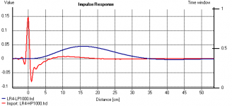
Here's another way of looking at it via impulse and pretty much what I do.
Below you will see the High and Low pass impulses of ideal Linkwitz-Riley 4th order filters @ 1KHz. With no delay or shift the peak of the low pass is 15.8 cm behind the high pass impulse peak. That's an ideal filter, computer generated.
If your acoustic slopes where both 1Khz, L-R 4th, then ideally your impulses would look like this. By moving one driver until the low pass peak is 15.8 cm (0.4 ms) behind the high pass peak, or as near as you can get them, then you've got the alignment right for that slope.
Of course you have to know the acoustic slopes of your driver sections, but that's another matter.
Attachments
Hi
Conceptually getting rid of the phase shift through crossover is desirable, it makes the time position fixed instead of moving around (as first discussed by Richard Heyser). The idea of making an upper and lower driver knit into one acoustic source is also appealing from a dispersion point of view.
About 12 years ago the company I worked for began selling a horn in commercial sound called a Unity horn that I had designed.
This was an attempt to sum several frequency ranges within a single horn body. These had good pattern control and less phase shift in the sum than the slopes would suggest but It wasn’t until about 7 years ago that I was able to make a 3 way passive speaker that appears to be one horn driver. This improved version is called a Synergy horn.
As suggested here, if that can be accomplished, reproducing a square wave is possible, if the drivers add coherently too, that is possible at any location in front of the cabinet and not just one location or one frequency.
Fooling around with square waves “back then”, a post here with some pictures.
http://www.diyaudio.com/forums/multi-way/71824-making-square-waves.html
Personally, I think Dave’s advice is sound (haha), it is the phase response that is the most useful indicator of where one is.
Normal crossovers look like an all pass filter (flat response with phase shift, upper range ahead of lower), when these Synergy style crossovers work, there is no phase shift.
Also, keep in mind that if one sums a normal crossover to make it nice and flat, then you offset the time and polarity to fix the step in GD, what you get now is not nice and flat. If you assign the upper and lower ranges to the same time and also try to get no phase shift, you don’t get any combination that works using normal named filters.
Also, while much of the world is in love with the idea of an impulse response, it is harder to read in many ways that a real magnitude and phase plot, it is a different view of that same information after all.
I have ARTA and like it but I have not used it for taking the crossover data yet.
For that data, I use a TEF machine. What I do is measure the hf driver’s ETC (energy vs time) and use it’s location at 20KHz to locate the “zero time” for the next step.
I take a TDS measurement which provides the hf drivers magnitude and acoustic phase, then, the mid and low sections but without re-setting the time reference. The TEF has a real phase detector and so preserves the phase relationships between the drivers and reflects the different locations they are in. These are used in the computer model.
I would guess that ARTA can do this but I have not used it for that.
Anyway, if you’re trying to make a phase shift free crossover, start in the computer.
Make two band pass filters, an upper and a lower.
Ponder the phase responses of each and think, how close do these phase curves have to be before the upper and lower band pass phases are say about 90 degrees apart (meaning they will sum with only a little gain hint hint).
When in doubt start with a higher order Bessel high pass and a shallower low pass.
Then, remember you are really going to be adding the filters responses to a set of driver’s magnitude and phase responses.
Lastly, in the computer, filters add like signals and resistors, the result is unilateral, coherent addition.
If you invert one of two equal signals, they cancel out. Drivers can do that too BUT that only takes place when the drivers are less than about 1 / 4 wavelength apart, they add coherently and feel each other’s radiation resistance.
Once the spacing is about 1 / 2 wavelength or more, the two sources radiate as individual sources and produce an interference pattern recognizable as a pattern of lobes and nulls. At 1 / 2 wl spacing one has a figure 8 pattern, the larger the spacing the greater the number of lobes and nulls. When radiating independently, if you reverse one of the two sources, the sound isn’t canceled out but the pattern of lobes and nulls is re-arranged.
For my work, this part was very important as in commercial sound one wants as much of the energy as possible to be in the front radiation and as little as possible outside. By getting all the drivers to add coherently in each range within the horn, a dusty old prototype 50 by 50 degree speaker like the one shown in the link above is still -20dB at 90 degrees off axis at 500Hz, about -10dB at 300Hz at 90 off.
Having all the drivers coherently sum puts the horn in charge of controlling the pattern over the entire band, no lobes (other than the one front lobe) and nulls, a much lower SPL to the sides and behind = a good thing in commercial sound, no phase shift through crossovers and close to a single point in time radiation = good for the ears.
Best,
Tom Danley
Danley Sound Labs
I'm a bit puzzled by attempts to measure acoustic offset (the OP) in various ways when there is a simple, straightforward way to do it that can be very precise. It does require taking the measurements and creating a reasonably accurate model of drivers and system (3-d space location of drivers and mic) in design software, but if one can measure, any of the design packages, purchased or free (Jeff Bagby's PCD being a prime example of the latter) will do it exceedingly well. From that point forward, it's a matter of designing the crossover in classic methods.
All one need do is make three measurements. I always have done it with raw drivers, even the tweeter, because it does not require high power at this point as it provides better S/N in the tweeter highpass area allowing lower power, although some prefer to use a cap on the tweeter. With a system that has a feedback probe, you place it at the tweeter terminals to eliminate upstream components, cap and anything else. There's an article at my site originally published in SpeakerBuilder ONE:2000 that describes this approach. It works every time. I've gone to the point of making adjustments of 0.1mm for the best fit.
Finding Relative Acoustic Offsets Empirically
Trying to use excess group delay has several issues that make it less than an accurate method. The method described above will work no matter the crossover, whether all-pass or constant power. There is no need to create a crossover first.
Dave
Edit: I'm sure that others had been doing similarly or maybe the same before I worked this out for myself. I had no internet access back then and access to publications that may have described it were not readily available to amateurs.
Yes, this is my favorite method. It works perfectly and it's very accurate, fast and easy to use.
I usually measure like this without moving the microphone or loudspeaker between measurements:
- Measure the tweeter at 1 or 2m distance at tweeter axis.
- Measure the woofer at 1 or 2m distance at tweeter axis.
- Measure the tweeter and woofer (reference measurement) simultaneous at 1 or 2m distance at tweeter axis.
- Import the “reference” measurement (tweeter+woofer), the individual tweeter and woofer measurement in a cross-over simulation software like e.g. LspCAD 6 Pro.
- Adjust the z-axis distance for the woofer until the total output (tweeter+woofer) frequency response matches the “reference” measurement. Then you have the relative acoustic offset between the drivers.
- If the measurement was performed at 1m and you want to simulate the drivers response at e.g. 2.5m, use trigonometry to calculate the distance difference.
It’s very simple give it a try.
Regards
/Göran
Last edited:
I beg to differ, empirical results dispute that. I've used this method since 1996 and never once had it fail to yield very accurate results no matter the crossover point. The crossover Fc has at times gone from 1500Hz to as high as 3500Hz. The relative acoustic offset remained unchanged and the measured result always closely matched the model summed response. If the measurements and models from them are made properly, it works.It is not possible to measure the acoustic offset between two drivers unless a specific frequency is given where the measurement should be fullfilled, because both drivers are having nonlinear group delay since they are fundamentally causal.
- Elias
Dave
Thanks keyser, for being one of the few who replied to get the point of my post.If I'm reading Simon's post correctly, he isn't really concerned with finding out if the crossover works properly, rather he wants to find the relative delay between drivers. Maybe not relevant in many practical cases, nevertheless an interesting exercise.
I think many others misread the purpose of my original post. I specifically said I was presenting (and looking for feedback on) a potential way of easily and accurately measuring acoustic centre offset of two drivers, besides the usual impulse method which isn't too reliable or accurate in practice.
I wasn't really looking for a debate on whether acoustic centre alignment actually matters or not, nor was I looking for a way to measure or design the phase tracking of a crossover.
Acoustic centre alignment and phase tracking are related but orthogonal problems. You can have acoustic centre alignment without phase tracking, you can have phase tracking (through the overlap region at least) without acoustic centre alignment, and you can have both (or neither!) at once.
Some people think acoustic centre misalignment doesn't matter, that's fine, however I'm still interested in ways of measuring it.
I'll reply to a few specific points in following replies. (I go away for one day and a whole raft of replies come though
)That's similar to one approach I tried, however I found it difficult to determine the tracking of phase and minimum phase accurately enough.What I ultimately did and how I'd do it now is use the highest possible sampling rate and put the marker well before the impulse of the earlier arriving driver. Then I use ARTA to get the minimum-phase - which I save as an overlay - and I look at the measured phase, which will contain a lot of excess phase rotations because the marker is placed well before the impulse. Consequently I estimate the time difference between the marker location and the start of the impulse and I enter the estimated value in the "delay for phase estimation (ms)"-window. Then I just keep fiddling with the delay to get the overlay of the minimum phase and the measured phase to be as close as possible.
Then I look at the second driver and I keep the same time-window. Again I'd save the minimum phase response as an overlay and experiment with the value in the "delay for phase estimation (ms)"-window to get the measured phase and the minimum phase to track as best as possible.
The final step is to subtract the values I had to enter in the "delay for phase estimation (ms)"-window and I have the difference in air-path delay.
If you're only checking the phase tracks through the crossover region, you're only checking phase tracking, not acoustic centre alignment. To compare the acoustic centres you need to look at the excess phase and see if the excess phase near the middle of each drivers passband has the same slope.It is not always possible to get the measured phase and the minimum phase to track each other perfectly over the entire bandwidth. Maybe that's because the sampling rate (192khz) is too limited or maybe the drivers aren't 100% minimum-phase over their entire bandwidths. I can usually get them pretty close though. With the dipole it moreover was only important close to the crossover-point, so I made sure the curves tracked well in that frequency region.
Near the crossover frequency the all-pass action of the summed filters will add its own excess phase, however far enough away from the crossover frequency in the middle of the driver passbands the only significant excess phase should be the linear phase introduced by the distance from driver to mic.
Excess group delay is excess phase differentiated, so an equal group delay at two different frequencies means the excess phase slope at both frequencies is the same. Thus excess group delay is visually much easier to compare on a graph than trying see if the excess phase has the same slope. Instead of looking for the same slope you're only looking for the same height on the graph. Same information, different visual presentation.
Interesting. Which marker are you referring to ? Start marker or end marker ?Of course this whole procedure is a lot more cumbersome than Simon's method. I think the idea makes sense. However, I tried his method and I don't get consistent results. The exact placement of the marker has a very significant effect on the measurement results. I don't understand why this happens.
Are you saying the results are not consistent from one measurement to another ? Or do you mean with different driver/crossover combinations ?
Do you have ARTA set to keep the same start and end markers between measurements ? I find that very helpful when repeating measurements, to ensure I don't put the markers in slightly different places. (File->Options->Retain cursor and marker position)
If you move the start marker between measurements, the "Delay for phase estimation" setting will become invalid.
I found very consistent results when I tested, even when reversing the phase of a 3rd order crossover when the drivers were aligned - the group delay peak is vastly different but the "saddle" on either side near the middle of the drivers bandwidths are almost identical, with an error amounting to less than 4mm difference in the calculated position.
Last edited:
Which brings me back to my first comment. To repeat, I'm a bit puzzled by attempts to measure acoustic offset in various ways when there is a simple, straightforward way to do it that can be very precise.Thanks keyser, for being one of the few who replied to get the point of my post.
I think many others misread the purpose of my original post. I specifically said I was presenting (and looking for feedback on) a potential way of easily and accurately measuring acoustic centre offset of two drivers, besides the usual impulse method which isn't too reliable or accurate in practice.
I'll add that this is for the specific driver FR models created, the models should not be altered later. A fixed model set is what one generally uses in the design phase anyway.
Dave
- Status
- This old topic is closed. If you want to reopen this topic, contact a moderator using the "Report Post" button.
- Home
- Loudspeakers
- Multi-Way
- Measuring driver acoustic offset using excess group delay ?