Seems like I remember an issue early on with the cviller boards and reverse orintation of the zetek devices? Its been a while, but it may bear checking it out.
Russellc
These are his V2 boards... I assumed he didn't make the same mistake twice. The orientation on the board of the V2 is the same as the corrected version of the first version. Regardless I have taken them out and I should test them. Can anyone tell me how?
erpiii
As a first, test the jFETs for Idss.
How should this be done?
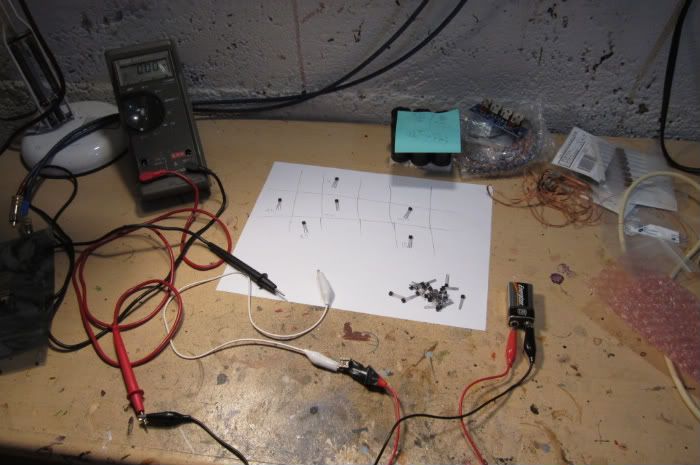
All you need is a 9v battery, a DMM and a couple of test leads.
The following was taken from here -- http://www.tangentsoft.net/audio/opamp-bias.html --
Testing a JFET's IDSS
It may not be obvious how to test for IDSS from the schematics above. The way I do it is to set up a solderless breadboard (a.k.a. plugboard) with a jumper across two rows. Then I plug the JFET into the board so that the jumper connects the gate and source pins. I then connect the negative side of a ~9V power supply to the jumper, then connect the negative lead of a milliammeter to the JFET's drain, and finally the positive lead of the milliammeter to the positive supply lead. The JFET saturates at its IDSS level in this situation, and that current value shows up on the milliammeter.
To get usable results from this test, your milliammeter has to have a resolution of at least 1 mA, and 0.1 mA or better is perfect. I recommend that you use a current-limiting power supply for this test because it's very easy to short the milliammeter across the power supply with a simple slip of the probe; if your power supply is capable of putting out more amps than your meter can handle, you'll blow a fuse in the meter. (Or if it isn't fused, you could destroy the meter!) DMM fuses are expensive and hard to find, so you don't want this to happen, trust me.
Once you have your breadboard set up for testing transistors, I recommend that you test a whole bag of them at once and keep them sorted somehow. That way you only have to do the test once, and then later you can pick matched Q1/Q2 pairs quickly. One way to keep your transistors sorted is to put them on a strip of tape, folded over the heads of the transistors, similar to the way some resistors and diodes come packaged. Masking tape works well for this. Another way is to get a small fisherman's tackle box, and use each compartment to hold parts within a small IDSS range; the kind with lots of small compartments works best.
I have only done this with N-channel devices, hopefully someone with more experience will chime in and say if there is any changes needed to test the P-channel...
Last edited:
I have this link
dont know if its good
Transistor matching
instant search on fet matcing, this came up
http://www.geofex.com/article_folders/fetmatch/fetmatch.htm
and a hell lot more
to achieve perfect matching you need very advanced equipment, and carefully controlled test conditions
but I guess you would be able to find/choose a close match, and have a good working pair
The first link is great! It really is simple...
great
Im very busy now myself, looking at other stuff I found
tonepad guitar effectsFor the more serious matcher without a curve tracer :
http://www.forsselltech.com/media/attachments/JFET_Jig1.pdf
Borbely's article also has a good match jig, but the article is no longer hosted.
Patrick
http://www.forsselltech.com/media/attachments/JFET_Jig1.pdf
Borbely's article also has a good match jig, but the article is no longer hosted.
Patrick
These are his V2 boards... I assumed he didn't make the same mistake twice. The orientation on the board of the V2 is the same as the corrected version of the first version. Regardless I have taken them out and I should test them. Can anyone tell me how?
erpiii
You likely right, but I dont think it was a mistake, original boards were not for zetek units...current BOM calls for zetek, so this shouldnt be it.
Russellc
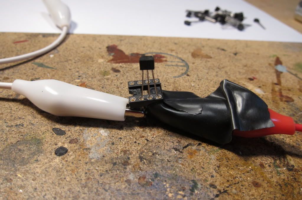
jFet Idss testing
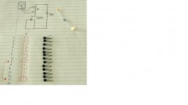
"John Curl: I hope that Nelson has shown how to do this, BUT it is fairly easy with just a multimeter. You just short the gate to the source and add a 9V battery from the drain to the source. This gives you Idss. But how to measure? Put a 10 ohm resistor between the drain and the battery and measure across it. 0.1V=10ma and so forth. Matching Vbe is much more difficult."
The picture is from Babowana's old website
Attachments
Last edited:
just to make it clear, I do not know this stuff
but from what I have been told, I doubt very much they will be that accurate
have you tried to measure them again, on a different day ?
on the good side, you might have several nice pairs, and not just one
btw, anyone ever tried to blow hot air on them, with a fan or something, to see if they follow each other, and change in unity ?
just to make it clear, I do not know this stuff
but from what I have been told, I doubt very much they will be that accurate
have you tried to measure them again, on a different day ?
on the good side, you might have several nice pairs, and not just one
Hi Tinitus,
Well, I found better accuracy with 100 ohm (then 1V=10mA) and most digital multimeters will give down to hundredths reading. I suppose one could warm the jFets to a specific temp for better matching. It should be good enough for sorting or approximate matching, if not precise Idss.
one , two , three , five
read
next
first I thought, sloppy zenmod
but then
this way you might actually take into account the temperature coeffciency, rise time factor, or whatever its calleddont say you didnt think of that
The methods described in post #11251 and #11254 are both very accurate.
The greatest contributors to inaccuracy are (in random order) :
1) Multimeter accuracy and resolution
2) Thermal drift of the JFET
3) Drift of your multimeter
To observe (2), put a low Idss JFET (say 7mA) on as described in #11251 for 5 minutes, and observe how the reading goes up and down, then breath on it, or just move your body away from the bench. If you have a 4~5 digit multimeter, you can see these effects quite clearly.
Single point methods only give you match at one point. See :
xen-audio
xen-audio
Patrick
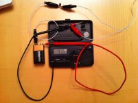
As a first, test the jFETs for Idss.
Using the method 6L6 supplied, I get 9.15 volts (new 9V batt voltage)... which I'm guessing means they are bad and I need new ones.
erpiii
Attachments
Have anybody looked into using a soundcard to make a simple curve tracer for this small signal stuff?
LR out could be used to sweep Vg and Vd and LR in to monitor currents. (of course with proper signal conditioning in between)
Even tough most soundcards are AC coupled the measurement could be done around a "known" manually set bias point.
LR out could be used to sweep Vg and Vd and LR in to monitor currents. (of course with proper signal conditioning in between)
Even tough most soundcards are AC coupled the measurement could be done around a "known" manually set bias point.
- Home
- Amplifiers
- Pass Labs
- F5 power amplifier