Nice work Algar, great attention to details, as always!
Btw, the Comar caps are model MKA 450-60
http://www.mgl.com.hk/mgl/documents/mka.pdf
Btw, the Comar caps are model MKA 450-60
http://www.mgl.com.hk/mgl/documents/mka.pdf
Dave, since you quote me: RTP3@Holger is mine and has serial number #22")
And i do hope you don't share your manual, i'm not going to share mine. My comment was amed at those asking for a copy of the CD.
dave
Previously, you could buy the RTP3C/D instruction CD by Allen for 100 €,The CD is the instruction manual that comes with an RTP kit. You get one by buying an RTP kit.
And i believe that if you want the disk, you should buy the kit, otherwize you are abusing Allen (and his heirs) innellectual property (ie being a pirate)
dave
which I did, but it is apparently no longer possible.


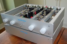
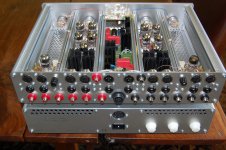
photos are of RTP3C PSU, algar_ami PSU is the RTP3D, which is quite different
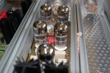
ceramic strips: Ettinger GmbH
ceramic strips: Ettinger GmbH
5/ If you want to build a RTP3D, then the full kit is the smart idea - but if you want to go for it by yourself, then for 100 euro I will send you the full instruction CDR that comes with the kit - it contains a LOT more than just the basic schematic that's on my website - like a full parts list.
Regards, Allen
Vince, damophi is right. I used to have the RTP3C PSU as well. Those pics are from emile (i think).
Last edited:
Not sure !
I think there are much more differencies...
Here the schematic rebuilt from the pictures Ive send yesterday.
By cheking twice, I found a mistake with my diodes. In fact, there is a full waves rectifier.
It is not possible too find out the component used by VSE.
As you see, the HV filter is very poor.
algar_ami, can you share and explain your schematic ?
vince
<snip>
As you see, the HV filter is very poor.
algar_ami, can you share and explain your schematic ?
vince
View attachment 251346
That appears to be a classic choke input filter, and knowing Allan I am quite sure that there is nothing "poor" about the high voltage power supply - you just don't have the full story..
The D version is using PCB, not point to point, and the same coupling caps as the SVP2 latest version, smd case size, Metallized polyphenylene sulphide type. These caps are also quite difficult to source in small order...
Problem with the ceramic strips is that you need to order quite a minimum, they sell only with bank transfer payment, etc...
So it is a costly affair. I ordered quite a lot at the time.
You'll get the same result, if not the same look using ceramic strip from Parts Connexion, see Connex Ceramic Terminal Strips
Allen never released the PCB design to kit form.
Check the 6moons review of the RTP3D review, and included pictures. You'll see the pcb and the capacitors.
I also used this review pictures to design my cases.
Attachments
Last edited:
fasterbyelan you cannot really build the phono preamp only. The phono is just the first section of the complete preamp. It needs the preamp section to present a fixed balanced 50K, and to provide the remaining gain.
The phono module just by itself is useless...
For the record, my preamp is not the real D preamp version, just my own approximation. You need to buy the real thing to get it...
Sorry, I won't share the schematic either. This is copyrighted stuff. I got my info from actual kit documentation, other RTP3 builders, and public domain websites and forums. I'm just describing the circuit in general terms.
As far as the power supply goes, don't get over board. It is using overspecs transformers, good diodes and caps and CRC and Choke supply filters. Nothing that cannot be designed using existing countless schematics on the net. For those with the C version supply, the D is really close, just add the heater supplies choke. Use excellent Duncan Amp PSU Designer software to find the correct values. And fit it inside a nicer enclosure. What you need to know is how to wire everything, heater line lifters, start ground, etc. But these are specifics to this very preamp as well. So you need to know how to build the preamp. Just the schematics won't tell all the story.
What you really need to design the supply is the real assembled preamp. I had to modify mine three times to correctly match the preamp needs since I didn't have the same parts.
For the record also take note that my cases are quite expensive and that I end up paying probably as much as what Allen asked originally for the cases kits. And it took me forever to make. Naturally, if the kit is no longer available, the diy route is the only alternative now... I'll certainly won't make an other one. Way to much work but it was quite an experience to built it.
Last edited:
As you see, the HV filter is very poor.
Far from it. You have only shown the raw B+ leaving out the all improtant SuperReg(s)
dave
Indeed, but using a good shunt regulator, for example the one from Emile design GB that I did a few years back (schematic for this one is on the thread), or even the simpler Salas shunt reg is a very good start. And the little details such as current regulator for the heaters, simpler little shunt reg for auxiliary supply, not mentioning the actual physical layout that certainly add to the circuit itself. It is a very sophisticated project to undergo. You really need the full set of instructions, images, parts list to be able to build it. I personally found quite a few errors in the document (I found quite a lot of errors in the DPA-300B kits instructions). But I guest this is normal. In all my life I never found a kit instructions manual without errors. These equipments are just to complex and the point to point assembly is prone to error anyway. Don't forget that Allen was continuously tweaking and improving his designs. I think that the kit instructions reflect the never ending modification process. Some errors in one set of instructions may be due to being obsolete in the current rest of the manual pages. So you also need to be able to find the errors yourself, and a good network of helpful contacts doesn't hurt either.
And VSE still sells its SuperReg kit Did you know that Emile worked with Allen to develop its own SuperReg? In fact Emile design is more sophisticated that Allen one. I'm not commenting on their respective sonic attributes though.
Here Emile Shunt regulator schematic with notes.
And VSE still sells its SuperReg kit
Did you know that Emile worked with Allen to develop its own SuperReg? In fact Emile design is more sophisticated that Allen one. I'm not commenting on their respective sonic attributes though.Here Emile Shunt regulator schematic with notes.
Attachments
Last edited:
Why is this choke filter not poor according to Allan Wright ?
vince
This is extremely ill informed and disrespectful I am afraid; for the reasons already pointed out to you. It is also likely that if Allen used the Lundahl choke as an input filter that he connected it in a way that allows some common mode filtering.
I made a quick survey:
Here 9V heater trafo are used. http://www.soton.ac.uk/~apm3/diyaudio/RTP3_building.html (And 3 different DC level!!!)
Others claim that they need 12V or 15V.
What choice did you take??? Isn't anything above 9V pure dissipation???
For HV transformers Allen used initially 2 x 250V, lateron he had 420V.
But:
With a raw calculation, the superreg needs 350V,
I would assume 160mA current, 2x 50Ohm in CRCRC, 130Ohm choke, total 230Ohm, is a voltage drop of around 40V. Even if I think of perfect infinity choke, 390V should be maximum...
A not perfect choke will end up with some ripple, even increasing voltage!!!
So RTP3D builders, what was your choice for what reason???
- Home
- Amplifiers
- Tubes / Valves
- Vacuum State RTP3C