Hi,
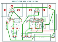
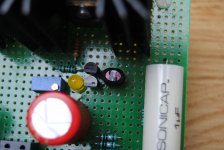
With a lot of help from Salas, I have just built myself a 18v Reflektor. Now powering a DAC and let it run in a bit before listening. First impression is not bad at all...
Please let us know your component´s choices and layout.
Just increased V12R current from 220mA to 290mA and the difference is substantial. I am powering my p2p DCB1 with it and sound became more detailed and with more control in the bass. Sounds "bigger" but detail is there. Much better separation than before.
I wonder how far could I go... is there a "ceiling" for this kind of improvement, or can I expect even better presentation if I increase current to 500mA ?
I wonder how far could I go... is there a "ceiling" for this kind of improvement, or can I expect even better presentation if I increase current to 500mA ?
Sorry geting lost here
Probably talking different SCH
There is no R12 or R11 in the Reflector is it?
Maybe be worth splitting treads?
About reflector I got one working as on SCH Salas posted for me (30V in 24V out) I got quite a few things to work out in my head so no worth posting so far...
...apart for thermal traking I think that the Current mirror transistor need to be thermaly coupled for better traking I mean goop and tie wrap so new lay out tomorow
Tanks Ricardo
Not your fault maybe tread shuld be splitted in 2 one for shunt original tread and one for
reflektor.
Tanks I have noticed qiute a bit of voltagge drift on a 450 Homs dummy load my current lay out will need to be changed.
Wuld it work better if all 4 the transistor in the mirror are tied togheter?
How you doing with other thing? Picture so far?
Tanks
Al
You should not see much voltage drift from a reflektor. Don't tie the 4, they work on different temp some of them. Q1, Q2 only. Try for Q1,Q2 best match on vbe, hfe. Try follow them for hfe in Q3. Also see if there is an issue with trimmer quality if using one instead of a resistor under the LED.

Yes.. sometimes trimmers are faulty... they may be the cause for noise and voltage drift.
I second that.
...And there are a lot of fake Bourns 3296 out there, which are carbon film instead of Cermet
The problem I think is cermet or plastic trimmers have a positive tempco, whereas carbon film ones have a negative one..... This can be a problem in some circuits for example if they're used to control shunt current : the less resistance, the more current , the more it gets hot, the less resistance, etc.....)
This is even more of a problem if you are running them close to the limit (I think 500 mW) especially if you're using only part of the resistive element surface to dissipate the heat (roughly when you're at 50% of the wiper position, you can only dissipate half the power rating, so the thing gets really hot...)
I had that issue on the Shunt regs from Twisted Pear... the trimmer is somewhat undersized, and with trimmers which I discovered later were carbon film, I saw the shunt current dangerously (slowly but surely) increasing, until I replaced it with a fixed resistor....
Last edited:
think of a pot or trimmer as having a current limit rather than a power limit.This is even more of a problem if you are running them close to the limit (I think 500 mW) especially if you're using only part of the resistive element surface to dissipate the heat (roughly when you're at 50% of the wiper position, you can only dissipate half the power rating, so the thing gets really hot...)
eg.
500mW 2k trimmer. Maximum continuous current I = Sqrt(P/R) = Sqrt(0.5/2000) = 0.0158A = 15.8mA.
That is the manufacturer's maximum recommended current to give specified life and specified performance.
Many including myself recommend continuous operating power at substantially below Pmax for certain performance and reliability advantages.
For resistors, including trimmers, I suggest <50% of Pmax, but lower limits are preferable to some designers/builders eg. 25% or 10% and in some critical locations.
For a 50% of Pmax limit the current must be reduced by a factor of sqrt(2).
That 15.8mA must be reduced to 11.2mA. No part of the trimmer can pass more than 11.2mA if you restrict your maximum rating to 50% of Pmax.
I am currently using a DVB-Projekt's boards in my TDA1541a DAC prototype. I will be moving to its final version soon, and want to integrate the regs on the main dac board (both for space and sound considerations). There are 4 power supplies needed: +5 (tda1541), +5 (reclocker), -5 (tda), -15 (tda).
I have 2 questions:
1. Which of the versions is best to use in this application (1.1, 1.2R, BiB, etc...) I lost track...
2. Would it be possible to cascade these regs? There is a connection inside the TDA1541 chip from the -5 to the -15V supply. Hence, it is advised to close this current loop between -5 and -15V externally by basing the -15V supply on the -5V supply (essentially a -10V on top of a -5V). Would that be possible with the Salas shunt? Or would the lead to oscillations? Or would it be possible by using a single CCS and two shunt parts?
Thanks!
There is much positive feedback about bib on digital, so use that. Better not cascade for reasons Andrew explained.
Thanks! I will be using BiB.
As my supplies used to be off-board, I had some decoupling caps very (3 mm) close to the supply pins of the TDA1541 (1 uF SMD film + 33uF BG + 270uF Oscon SEPC). Now that I will be placing the shunt regulators on the same pcb as the dac circuit, how can I best arrange this decoupling?
The BiB uses 2 caps on the output (part of the Zobel). Should I just place these caps very close to the chip and omit the decoupling caps I use now? OR should I use the caps on the output of the supply reg and in addition use a decoupling cap close to the chip? OR should I use the current decoupling caps as a replacement for the zobel caps of the shunt reg?
- Status
- This old topic is closed. If you want to reopen this topic, contact a moderator using the "Report Post" button.
- Home
- Amplifiers
- Power Supplies
- The simplistic Salas low voltage shunt regulator