@ Michael perhaps average would have been a better descriptor and please keep in mind i'm talking about average for a monolithic chip, i was actually comparing to opa1632 and ths4131 at the time i was considering it
input z of only 5k vs 34 Mohm
cmrr of only 65db vs 90db
thd when driving a pretty easy load of 600r is only 101
noise of -101
slew rate 15v/us vs opa1632 50v/us
opa1632 has olg of 78, which i find pretty impressive
the opa1632 has a very neat servo mechanism same as its heritage in SuSy
several others including se in bal out thd and in particular the that chip has outputZ of 50R!! versus 0.3r for the opa1632 50r is worse than average, for an opamp or even the average discrete cct thats unacceptable imo it was seeing this spec that caused me to look no further at the time
Last edited:
OPA1632/THS4131 (full differential amp manufactured by Texas Instruments with topology licenced from Mr. Pass) is basically a UGS modul confined to single chip. I love the way it sounds and I use it whenever I need unbalanced to balanced conversion (it's not hard to devise a similar discrete circuit but THS4131/OPA1632 is really hard to beat).
I used it in my version of circlotron with success:
http://www.diyaudio.com/forums/pass-labs/157915-simple-cirklotron-lateral-mosfets.html#post2034724
Juma, can the front end (up to the 1.5 uF caps) of the linked schematic be used for a self standing preamp/unbal-to-bal converter? Maybe with a suitable pot ......
Thank you!
P.S. what's the real difference between OPA1632 and THS4131? The latter costs nearly the double at mouser.
@qusp
I appreciate your comments and analysis.
Taken as a general purpose device, I see where you're coming from.
I was looking at it from the very narrow standpoint of adding an expedient (albeit a chip) unbalanced input to the circlotron, in which case I saw fairly good performance (<.002% THD) at the few volts required to drive the amp to full power.
I'm very interested to see what you guys do with these "Pass" chips. I had no idea they existed.
Thank you,
Mike
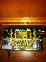
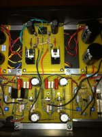
Here are a few pictures. It's a bit of a utilitarian construction, but it works, which is the main thing!Chris,
Can we get some pictures?
Gyuri
Chris
Attachments
Of course it can - just put a 10k/25k volume pot in front of the JFET buffer an you are redy to go.Juma, can the front end (up to the 1.5 uF caps) of the linked schematic be used for a self standing preamp/unbal-to-bal converter? Maybe with a suitable pot ......
There are slight differencies in DC offset setting circuit (Vocm) but that's hardly important. Chips are practically the same except that THS4131 is a new production (made after the deal with Mr Pass has taken place) so I suppose that's the reason why it costs more....P.S. what's the real difference between OPA1632 and THS4131? The latter costs nearly the double at mouser.
Many thanks for the comment! By the way, I've now determined that the hiss I reported hearing is entirely due to the linestage preamp; the circlotron itself is absolutely silent.I think it looks fantastic.
Gyuri: Well I suppose I did more or less copy the construction style I used for my OTL based on Tim Mellow's design:
Chris
Attachments
@qusp
I appreciate your comments and analysis.
Taken as a general purpose device, I see where you're coming from.
I was looking at it from the very narrow standpoint of adding an expedient (albeit a chip) unbalanced input to the circlotron, in which case I saw fairly good performance (<.002% THD) at the few volts required to drive the amp to full power.
I'm very interested to see what you guys do with these "Pass" chips. I had no idea they existed.
Thank you,
Mike
kinda OT/
Indeed Michael, if looking at it specifically for this place in this circuit its only marginally worse, although the inputz of 5k is likely to load the previous circuit somewhat, its manageable. taken with a more broad stroke its no contest.
they also sound incredible and will drive a variety of headphone loads directly without complaining. i have used them mainly in IV stages with gain and line drivers. they run a little hot and the 150ma output spec therefor is a little optimistic, but 100ma is no problem, perhaps i worry too much
these chips are also capable of pretty decent operation with a single supply which is handy. definitely worth a look if you can stomach an ic if it works and sounds well
gotta watch calling them pass chips though, as although Nelson received some payment from Ti, it was not in the form of wages; his 'wages' came from the legal department and his involvement was only after production began, if you catch my meaning

but you need only look at the internal schematic to see the resemblance
/end of OT
i look forward to starting this project, i already have balanced source, but you'll see the opa1632 and ths4131 featured. i just need to get some suitable transformers for the build, i'm going with the semisouth version. do you think i will have trouble paralleling the outputs if i up the current on input using one of euvl's to92 heatsinks? i'm not sure i'll even need to given the increase in power possible with the ss, so i'll just go with the 'stock' version first.
no Mike, Thank You!
Last edited:
Well, Chris, you're a true artist of DIY.Gyuri: Well I suppose I did more or less copy the construction style I used for my OTL based on Tim Mellow's design:
Chris
So much that I decided, I make an amplifier such as that you do.
(Maybe this is not just me at this place would have had to say.
Here now because I thought the OTL.)
However, if someone put his foot to Papaland, not an easy to release.
I present to you one of my Amplifiers:
http://www.diyaudio.com/forums/pass-labs/164003-so-my-quad-zv9.html
I also recommend that you build this.
Last edited:
Part choice..
Hi folks,
I read the article and the thread related to the circlotron and will give the build a try.
Is there any reason not to use wirewound resistors for the power resistors ?
Are the values of 100 Ohm and 0.47 Ohm (3 Watt each) critical for the design ? I am asking because I have some 0.56 and 0.82 in my drawer.
Anty reason not to go higher on the supply rails ? I would have some 24V secondaries on the shelf as well...
Cheers,
Max
Circolotron build
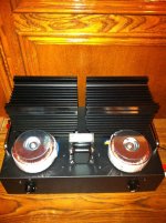
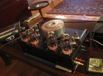
A vanilla Amazing FET Circolotron build. JFETs are 2SJS109BLs and the MOSFETS are matched FQA19N20C pairs. The resistor pairs are also matched. I opted to inset the top panels inside of the boxes rather than secure them to the tops of the boxes. (The panels are one half inch narrower in width and height.) So far they sound nice. After a couple of weeks, I'll measure them.
Michael, thanks much for all the hard work in putting this project together!
Dan
A vanilla Amazing FET Circolotron build. JFETs are 2SJS109BLs and the MOSFETS are matched FQA19N20C pairs. The resistor pairs are also matched. I opted to inset the top panels inside of the boxes rather than secure them to the tops of the boxes. (The panels are one half inch narrower in width and height.) So far they sound nice. After a couple of weeks, I'll measure them.
An externally hosted image should be here but it was not working when we last tested it.
An externally hosted image should be here but it was not working when we last tested it.
Michael, thanks much for all the hard work in putting this project together!
Dan
Nice build, Dan. The potted transformers look good.
thats what i thought initially too, but i'm thinking its just a regular transformer in a can, the outside looks metal.
for those impatient Michael has documented the R100 circ on his DIYA blog using these boards and it is indeed pretty much identical
Correct -- it's just a transformer in a can. A very heavy can. It's a 300 VA transformer from Antek with one of their well constructed cans. My only grip with the can was that it was supposedly powder coated. While that may be the case, it wasn't a very durable coating. While I had had it for about three weeks (and hence the coat was at least three weeks dried/cured/whatever), it would scratch just by my looking at it. So, I had to refinish both cans. However, I'd buy them again should I need/want them as they are very well built. And, I'm quite satisfied with the Antek transformers I've used.
Dan
Dan
- Home
- Amplifiers
- Pass Labs
- The Amazing Fet Circlotron by Mike Rothacher