See page 30 for the pin layout of the connector.
CCW means counter clock wise.
Thank you, that's make sense with connectors sent by TP
It's the right pin, right?
Attachments
Thank you, that's make sense with connectors sent by TP
It's the right pin, right?
CCW right pin?
Buff 3 build
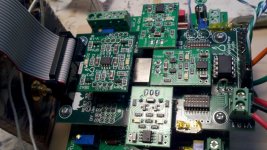
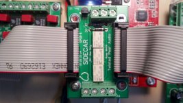
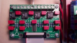
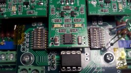
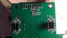
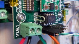
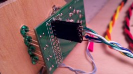
I have been assembling the buff 3 kit with the sidecar, mux and no volume pot. I cant get a signal lock. The mute led is on always. Jumpers 1-12 installed, switches set off except sw2-8 is on. Jumper to bypass volume control. 75R on mux for spdif. I'm not sure of the input selector wiring, no manual. The input selector changes the leds but no sound or lock.Theres some pics. Any idea what I am forgetting?
I have been assembling the buff 3 kit with the sidecar, mux and no volume pot. I cant get a signal lock. The mute led is on always. Jumpers 1-12 installed, switches set off except sw2-8 is on. Jumper to bypass volume control. 75R on mux for spdif. I'm not sure of the input selector wiring, no manual. The input selector changes the leds but no sound or lock.Theres some pics. Any idea what I am forgetting?
Attachments
-
 buff 3 conn (800x451).jpg315.5 KB · Views: 531
 -
 sidecar conn (800x451).jpg249.8 KB · Views: 518
 -
 mux conn (800x451).jpg273.6 KB · Views: 510
 -
 sw1 sw2 settings (800x451).jpg307.9 KB · Views: 501
 -
 buff 3 jumpers (219x124).jpg14.4 KB · Views: 293
 -
 vol control jumper (800x451).jpg250.5 KB · Views: 285
 -
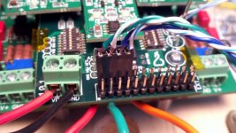 I-O conn (800x451).jpg262.9 KB · Views: 294
 -
 2-8 conn (800x451).jpg226.3 KB · Views: 298
 -
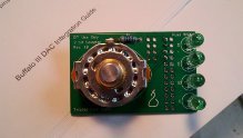 buff 3 input sel fr (219x124).jpg13.4 KB · Views: 278
That is correct. It says you need to connect the SPDIF wires to + and - on the module. For SPDIF you do not use the GND connector on the module.The guide said not to connect ground on Spdif.
buff 3
That was it. That's what happens when you work way too late on a kit trying to get it up and running. I thought it was weird to not have a second wire on the Spdif. I am listening to the buff 3 finally. Sounds great. Thanks for pointing me in the right direction. I have the 75r on the bottom of the mux to make it easier to change later. The legato 3 plays fine without caps on the output with the pass labs aleph 30 amp.
That was it. That's what happens when you work way too late on a kit trying to get it up and running. I thought it was weird to not have a second wire on the Spdif. I am listening to the buff 3 finally. Sounds great. Thanks for pointing me in the right direction. I have the 75r on the bottom of the mux to make it easier to change later. The legato 3 plays fine without caps on the output with the pass labs aleph 30 amp.
Thank you, that's make sense with connectors sent by TP
It's the right pin, right?
CCW right pin?
bump
")
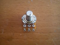
Finding which pot connection is CCW and which is CW is pretty simple. Just turn the pot completely one way or the other. Then measure the resistance between the wiper and each side. The lowest resistance matches that direction's extent. Easy right?
Thank you Russ
My guess would be 23rd October when the TPA guys come back from vacation.Is there an eta on IVY availability?
I'm hoping for news on AC2 and the differential I2S line module(s).
Cheers,
Nic
I'm interested in any opinions from BIII users as to the exact meanings and effects of some of the switch settings.
I'm only using SPDIF input, mostly red book. So what effect do these settings have, or are they even relevant?
- Quantizer setting
- Differential mode
- FIR Roll off (and what does this filter do exactly?)
Thanks for any input..
I'm only using SPDIF input, mostly red book. So what effect do these settings have, or are they even relevant?
- Quantizer setting
- Differential mode
- FIR Roll off (and what does this filter do exactly?)
Thanks for any input..
can somebody confirm that this is the replacement part for the ribbon connector for sidecar
thanks.
http://www.molex.com/webdocs/datasheets/pdf/en-us/0906351202_RB_CBL_WR_TRP_CONN.pdf
thanks.
http://www.molex.com/webdocs/datasheets/pdf/en-us/0906351202_RB_CBL_WR_TRP_CONN.pdf
Something like this would work just fine:
15-44-5820 Molex Headers & Wire Housings
Then just a 2 x 10 2.54mm pitch standard male pin header for the other side.
Here it's what have been confirmed already.
However, you can just use a glue for broken ribbon connector, if you broke a clips in a female.
Last edited:
- Status
- This old topic is closed. If you want to reopen this topic, contact a moderator using the "Report Post" button.
- Home
- More Vendors...
- Twisted Pear
- Buffalo III - flexibility without compromise.