Saturday Homework:
I want to have at least 220mA in the CCS so I am using 3r3 // 10r instead of 4r7 for R1.
R4 = 82r (I do not have such value so I will try 100r)
The 470u BG std on the input is good for decoupling.
R7 (0.22r) will be done with 4 x 1r (R7 a-d)
The output zobel cap (1u) is placed on the edge of the board so I can easily replace it (I want to try 220nF FT-3)
For C2 I will try 680u BGN that I have left over.
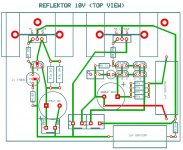
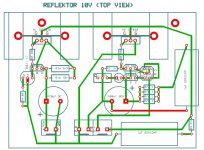
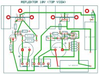
I would apreciate your oppinions on the layout and particularly on the Mosfet connections because I am not sure I got M2 Drain and Source well connected... Does M2 Drain go to F+ ?
I want to have at least 220mA in the CCS so I am using 3r3 // 10r instead of 4r7 for R1.
R4 = 82r (I do not have such value so I will try 100r)
The 470u BG std on the input is good for decoupling.
R7 (0.22r) will be done with 4 x 1r (R7 a-d)
The output zobel cap (1u) is placed on the edge of the board so I can easily replace it (I want to try 220nF FT-3)
For C2 I will try 680u BGN that I have left over.
I would apreciate your oppinions on the layout and particularly on the Mosfet connections because I am not sure I got M2 Drain and Source well connected... Does M2 Drain go to F+ ?
Attachments
Q1,Q2 reverse so they look to each one's face so you can bond them for same temperature. See they have the best hfe & Vbe matching also.
I will do that , thanks. What type of glue should I use ? Or can I use thermal compound and fix them with termal sleeve ?
Can I use metal film 220r for gate stoppers or should I go for CF ?
Is R3 2.2r determinant or can I use 1r8 ?
Last edited:
Gate stoppers MF OK, worked with other regs with comparable gain and frequency too. Have some space in case a base stopper for Q5 is going to be needed in the end, there is some layout distance that may demand it. No glue! Thermal grease and thin tie wrap or heat shrink sleeve.
1.8R looks safe (theoretically). If it proves very stable, we can look if it will be stable with only 220nF teflon zobel cap also. But don't start with too many changes, in case it will not go well, to know where to experiment step by step.
1.8R looks safe (theoretically). If it proves very stable, we can look if it will be stable with only 220nF teflon zobel cap also. But don't start with too many changes, in case it will not go well, to know where to experiment step by step.
Thank you Merlin
You have e-mail.
I have a box full of 220nF FT-3... do you want some to experiment ?
Ricardo you have email, thanks for the couple of caps.
")
Good idea:
In this case I left place for the Q5 Base stopper (120r ?)
I compared this layout with the V1.2 and see that in that case the power mosfet has the Drain connected to F0.
In the Reflektor, the power mosfet Drain is connected to F+... Why ?
In this case I left place for the Q5 Base stopper (120r ?)
I compared this layout with the V1.2 and see that in that case the power mosfet has the Drain connected to F0.
In the Reflektor, the power mosfet Drain is connected to F+... Why ?
Attachments
I have tried to implement a Salas shunt for providing the B+ of my Aikido LV, which runs on 24V. It contains 4 tubes, so current draw is less than 10 mA. Input voltage to the SS is 31V, which is on the low side, but should work I think, no?
Unfortunately, it doesn't work. The CCS works (the 3 leds light up, and I measured 2.3V across the 10Ohm resistor, giving 230 mA). However, the 2 leds for the shunt part don't light up, and output voltage is 0.
-What can be the problem? I have used the same board for 5V regulation and just changed the trimmer resistor and input voltage to make it 24V (which works when I disconnect the load).
- How can I troubleshoot?
thanks!
Last edited:
Are you sure LED are proper oriented or are possibly damaged?
None of the above...
- Status
- This old topic is closed. If you want to reopen this topic, contact a moderator using the "Report Post" button.
- Home
- Amplifiers
- Power Supplies
- The simplistic Salas low voltage shunt regulator