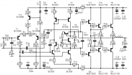
C9(47uF) forms an RC filter together with R14(33 Ohm).Hi all.
Someone could explain the function of C9. Improves sound?
Thanks
This stops ripple and hum on negative rail to reach frontend of amp.
So, it keeps disturbance from power supply to get into the operation.
A couple of Maplin amplifier modules.
An externally hosted image should be here but it was not working when we last tested it.
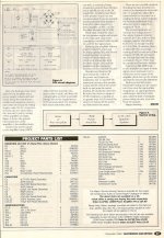
MAPLIN 160W/225W BIPOLAR TR. MJ2955 AND 3055 AMPL. GALLERY
I built mine about 1980 from a Maplin kit.
I used two heatsinks instead of one as I used it for a disco and it was pushed hard. Never let me down and always ran cool even when pushed hard.
Very loud.


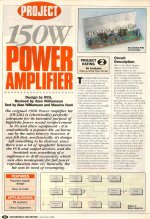
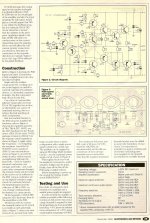
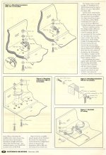
Here are the pages from the magazine article. Note, these are for the later (mk2) version of the amplifier. The original had a lot of wiring between the heatsink and the circuit board, as well as you had to drill the heatsink yourself. This version substitutes an L-shaped metal bracket similar to what the 50w bipolar and 150w MOSFET amps used.
As for the comments about Maplin turning into Tandy, it really is a shame. If only they'd just make their excellent PCBs available again, the components you can get pretty much anywhere (for this amp at least).
Back in time, Tandy was once a good place to buy electronics. I remember a kid at school gave me a kit he'd got from there, and could never build. He'd soldered two capacitors on the board, without trimming the leads down, and the soldering looked like pidgeon pooh, before he gave up. It was a quasi-complimentary design using two 2N3055s, I finished it off and added a power supply, and it worked well for many years.
Lee.
Attachments
Thanks for the mk2 Maplin amp article, I didnt know they did a mark 2 version.
I used the mark1 version on my mobile disco but used it with two heatsinks instead of the one recommended and it ran cool.
I cheated with the heatsinks as they were bolted to a woonden box I didnt need isolating tabs.
A bit naughty as the heatsinks hung out the back of the box lol
I used the mark1 version on my mobile disco but used it with two heatsinks instead of the one recommended and it ran cool.
I cheated with the heatsinks as they were bolted to a woonden box I didnt need isolating tabs.
A bit naughty as the heatsinks hung out the back of the box lol
Last edited:
dear nigelwright7557,
do you have any d.j.sound amplifier circuit now days plz send me my e mail is alvi.masood251@gmail.com.yours ever masood.
do you have any d.j.sound amplifier circuit now days plz send me my e mail is alvi.masood251@gmail.com.yours ever masood.
Thanks Lee.
I recall the original having BFY51's and so on - never did know how the original managed to work above about 40V except that the base and emitter resistors of Tr5 keep the gain very low (base=220 ohms, emitter=100 ohms) and to compensate the input diff pair have to work at a rather higher current than is necessary.
This design could be improved now that it uses BD139's for the VAS - and in principle should also be able to use BD149/BD140 pair for the drivers, not the slow BD711/712 pair.
50V rails is I suspect too high for safety, even though I have often mentioned that the original 2N3055 spec. requires 100V transistors in the epi base technology to meet the RCA standard 100V Vcbo. I'd keep the rails below 45V which is fine for 70W into 8 ohms.
Using a resistor-capacitor decoupled supply in the tail of the diff pair is usually asking for trouble in the form of turn-on thumps.
I'd use R4 for the emitter of another PNP , connecting the collector to the emitters of the diff pair, and adding two diodes and a bias resistor across the Zener, but the values of R4, R3 and R13 should be changed.
C5 could then be omitted, and R8 (?), the bias resistor of the current source to the VAS, can be changed and connected to ground.
C3 across the Zener can be reduced to something like 10 nF, which avoids large time constants. These mods. remove all the large time constants which could cause thump (it is noted that C5 may help by keeping the current low initially) and allow the diff pair to reach operating current at a low power supply voltage.
R 3 could be 680 ohms and D1 disconnected from R3, but kept in place and adding a second diode in series to th enegative rail would provide a current limit clamp for Tr5. R13 could be 10 ohms.
For a couple of extra capacitors and diodes in the power supply, a double voltage negative rail could be provided allowing R14 to be connected to it so that the input stage is not a limiting factor. It is also better for Tr5 not to saturate first, as this keeps the phase correct in clipping, but these are not such important mods. for a generic PA amp.
However, the previous mods should allow the VAS gain to improve and reduce overall distortion to around 0.02% rather than "<0.1%".
John
dear nigelwright7557,
do you have any d.j.sound amplifier circuit now days plz send me my e mail is alvi.masood251@gmail.com.yours ever masood.
An externally hosted image should be here but it was not working when we last tested it.
dear neil wright sir,
i have just buit one 50w maplin amplifier mini kit but there is a problem,when i switch on the transistor r23,r24 and tr.q10 and q12 began to warm and preset r12 2.2kohm not work while i replace r11 4k7 to 3.9 .power supply is by 15-0-15 volts transformer.how can i measure voltages at various point.thanking you curiously in waiting your reply thanking you.
your's ever masood
dear nigel wright,
please send me reply of above quoted question.please send the wiring diagram of ht1,ht2,ov1,0v2 ht3,ht3 can this will be shorted ht1 to ht2 , 0v1 to 0v2 and ht3 to ht4 thanking you ,yours ever masood
I dont have any more information on that amplifier. Try a search of DIYAUDIO, i think I saw it somewhere.
- Status
- This old topic is closed. If you want to reopen this topic, contact a moderator using the "Report Post" button.
- Home
- Amplifiers
- Solid State
- Maplin 160W (225W) bipolar amplifier design