I think my question regarding the types of feed-back to use in the "best sounding" amplifiers was not well understood.
There are some designers (and also some customers) that believe that the negative feed back affects the sound in a negative way. For mid fi or hi fi, it is not a problem, but for the "world class" amplifiers, where every "coloration" matters, it is a problem.
If I'm not mistaken, Charles Hansen supports the idea that no feed back (or low feed back) amplifiers are preferable to those who use global feed back.
Also, John seems to be a supporter of this idea, probably less so than Charles.
N.P.'s designs often have low or no feed-back.
And there are others supporters, of course.
Given all that, my initial question was: what kind of feed back do these designers believe it is o.k. to use in those amplifiers that "reach for the sky" (not mid fi or hi fi).
They might believe, for example, that the global feed-back is definitely to avoid, degeneration is ok and cannot be reasonably avoided, and local feed back is probably best avoided if possible.
Of course, such advice would not be universally accepted by other designers.
To satisfy my curiosity about "the sound of feed back", I thought of making an amplifier that only uses degeneration but no local or global feed back. I think it would be interesting to hear such an amplifier and form a personal opinion on "the sound of feed back".
Maybe it exists, maybe not (or at least, not for my ears).
Any advice will be appreciated.
The fact that a stable loop must have "integration" in it pertains to the fact that loop gain goes through 0dB before phase goes round the clock, not that loop gain must necessarily go all the way to infinity at DC. In fact practical integrators always level off at some point where they reach their DC gain. With a degenerated transistor this just happens at a high frequency so for most of the band it appears almost like a P controller with no integration. In reality though there are NO true P controllers. Every physical has a bandwidth limitation i.e. some HF poles. Witness the fact that some follower circuits oscillate quite happily. Those that don't will upon close inspection turn out to have a dominant pole. It just happens to be real and well in the megahertzes. And yes, this loop has a transfer function (or complex function as you call it) just like any frequency dependent system, and it's written mathematically as a horizontal line with a polynomial below it and a shorter one above it.
Back to hiding, Jan Didden asked me to chip in so I hope this is more or less the answer he was looking for.
May or may not be what Jan was looking for, but exactly what I was looking for. THANK YOU. And more thanks to DF96 "No one could steer me right but (you and) Mama tried". THANK YOU.
So there's nothing special about degeneration or single-stage feedback in general except open loop bandwidth. Like a lot of folks have been saying, but without this piece of the puzzle. Clear and important.
BTW, loved your LA article - infuriating is the word that comes to mind! Arf.
Thanks again,
Chris
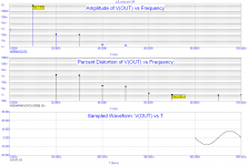
If the 1M FB resistors are omitted, low order distortion remains the same, but high order distortion components rise.
Pictures or numbers please, or are you going to make me eat my shoe like Wener Herzog. I might note your circuit is not the original.
Wait a second guys, the harmonics above thirds start at 40dB below the thirds. This could be splitting hairs and random numerical cancellation after all is is a different circuit and just a sim. What about the seconds and thirds also from the same sources of distortion?
PMA's results actually prove our point the dominant distortions from soft voltage coefficient non-linearities are not reduced by this resistor, whats happening at the ppm level is dependent on all kinds of fortuitous non-fortuitous cancellation.
I'm beginning to smell krill. So have fun guys, not getting sucked down that again.
Last edited:
I think my question regarding the types of feed-back to use in the "best sounding" amplifiers was not well understood.
In the group you address, I don't think there is as much consensus as you
hope. I only gave you my own opinion.

care to post/point to spice models to be used in this "fair" simulation?
I'm sure anything Scott or I chose would automatically be suspect as "bad" models - certainly after the fact if the results don't match your expectations - or will the fall back position be "these effects are too subtle to be modeled after all"?
JCX, often agree with your posts, but not quite on this one. I have been cook-book engineering with opamps since the beginning of the eighties, calculating the stuff through by hand. Then the Spices come along, and I work with them intensively. Sims are great for intellectual ping-pong, however, real world results hardly ever match.
So "effects to subtle to be modelled at all": if my sims only correspond so-so with the measured performance, I certainly would not put my money on sims bringing out the sort of subtleties we can percieve as human beings.
Let me put it in another way. Sims are based on a solid understanding of the basic interactions between the different electronic components. State of the art. And however advanced, while keeping within that mathematical model, you will never be able to enhance the state of the art. Sims by definition force you into that. Gödel all over again.
So, the only thing that works is theory, experimentation and measurement, adaptation of theory if needed, full cycle and ready to go again. This discussion has been a little short on experimentation and measurement.
vac
"krilled"?? - is that like being Rick rolled?
I guess it must be the models - I used fet models from http://www.diyaudio.com/forums/parts/18031-looking-spice-models.html#post210374
Cordell's Q models, maybe Bob's (skeptical) touch "spoils" the sim?
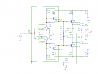
all the part models are on the schem
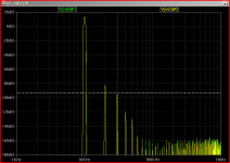
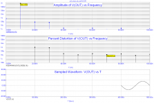
the result is, again, No difference in distortion or distortion "profile" with the the output in Class A with or without the inner feedback 1 M resistors - down to -170 dB below the fundamental
when bias is cut back a little, edging into AB output operation, removing the inner feedback Rs reduces some higher harmonics
I am getting tired of this - my impatience may mean there are errors in the sim - find them, put up PMA's models or work the excuse list a little harder...
I guess it must be the models - I used fet models from http://www.diyaudio.com/forums/parts/18031-looking-spice-models.html#post210374
Cordell's Q models, maybe Bob's (skeptical) touch "spoils" the sim?
all the part models are on the schem
the result is, again, No difference in distortion or distortion "profile" with the the output in Class A with or without the inner feedback 1 M resistors - down to -170 dB below the fundamental
when bias is cut back a little, edging into AB output operation, removing the inner feedback Rs reduces some higher harmonics
I am getting tired of this - my impatience may mean there are errors in the sim - find them, put up PMA's models or work the excuse list a little harder...
Attachments

Last edited:
John seems to find servo feedback to be kosher. To your list of global, local, and degeneration, I think you should also add global servo feedback as a type to track.There are some designers (and also some customers) that believe that the negative feed back affects the sound in a negative way. For mid fi or hi fi, it is not a problem, but for the "world class" amplifiers, where every "coloration" matters, it is a problem.
If I'm not mistaken, Charles Hansen supports the idea that no feed back (or low feed back) amplifiers are preferable to those who use global feed back.
Also, John seems to be a supporter of this idea, probably less so than Charles.
I don't know if the word 'often' is accurate. Perhaps for the commercial designs? I surveyed the public schematics and found 27 articles with circuits employing feedback. That list notably includes the F1 and F5 products. Unless I am mistaken, the following articles mention feedback (if the abbreviations are undecipherable, check my Guide): CAA, A40, CAS, C12, A75, ZEN, ROZ, SUSY, DOA, POW, ZV1, ZV2, ZV4, XA, MOS, ZV5, F1, F5, ZV6, ZV7, ZV8, PLH, ZV9, DIST, BA1, BA2, SWEETN.P.'s designs often have low or no feed-back.
You might have trouble with DC offset if you don't use servo feedback. So, I wonder, what is the sound of excessive DC offset in amplifier? Is it the cracking of the cone as the windings melt?And there are others supporters, of course.
Given all that, my initial question was: what kind of feed back do these designers believe it is o.k. to use in those amplifiers that "reach for the sky" (not mid fi or hi fi).
They might believe, for example, that the global feed-back is definitely to avoid, degeneration is ok and cannot be reasonably avoided, and local feed back is probably best avoided if possible.
Of course, such advice would not be universally accepted by other designers.
To satisfy my curiosity about "the sound of feed back", I thought of making an amplifier that only uses degeneration but no local or global feed back. I think it would be interesting to hear such an amplifier and form a personal opinion on "the sound of feed back".
I guess it must be the models - I used fet models from http://www.diyaudio.com/forums/parts/18031-looking-spice-models.html#post210374
Cordell's Q models, maybe Bob's (skeptical) touch "spoils" the sim?
all the part models are on the schem
the result is, again, No difference in distortion or distortion "profile" with the the output in Class A with or without the inner feedback 1 M resistors - down to -170 dB below the fundamental
when bias is cut back a little, edging into AB output operation, removing the inner feedback Rs reduces some higher harmonics
I am getting tired of this - my impatience may mean there are errors in the sim - find them, put up PMA's models or work the excuse list a little harder...
Thorsten has succeeded in creating a hate the objectivist atmosphere since he couldn't revive the tweakers forum, touche.
The fact that a stable loop must have "integration" in it pertains to the fact that loop gain goes through 0dB before phase goes round the clock, not that loop gain must necessarily go all the way to infinity at DC. In fact practical integrators always level off at some point where they reach their DC gain. With a degenerated transistor this just happens at a high frequency so for most of the band it appears almost like a P controller with no integration. In reality though there are NO true P controllers. Every physical has a bandwidth limitation i.e. some HF poles. Witness the fact that some follower circuits oscillate quite happily. Those that don't will upon close inspection turn out to have a dominant pole. It just happens to be real and well in the megahertzes. And yes, this loop has a transfer function (or complex function as you call it) just like any frequency dependent system, and it's written mathematically as a horizontal line with a polynomial below it and a shorter one above it.
Back to hiding, Jan Didden asked me to chip in so I hope this is more or less the answer he was looking for.
Hi Bruno,
Well-stated. Nice to see you here.
Cheers,
Bob
I guess it must be the models - I used fet models from http://www.diyaudio.com/forums/parts/18031-looking-spice-models.html#post210374
Cordell's Q models, maybe Bob's (skeptical) touch "spoils" the sim?
all the part models are on the schem
the result is, again, No difference in distortion or distortion "profile" with the the output in Class A with or without the inner feedback 1 M resistors - down to -170 dB below the fundamental
when bias is cut back a little, edging into AB output operation, removing the inner feedback Rs reduces some higher harmonics
I am getting tired of this - my impatience may mean there are errors in the sim - find them, put up PMA's models or work the excuse list a little harder...
I have full confidence in the outcome of these sims on the dimension you are modelling.
What I am interested in doesn't show up in these sims, and I don't know if it can be done. Phase modulation is the key word here, looking at the reality of a musical signal. An example in line with that: a 50Hz combined with a 2Khz 20 dB below. Would there be any phase shifts in the 2 Khz tone, as a function of the 50 Hz tone? And would there be differences between the different feedback topologies in this respect?
It is a mind twister I have been walking around with for some time. Just suppose the 2 Khz tone gets advanced by x degrees on the upward slope of the 50Hz tone, and gets delayed with the same amount on the downward slope: this would equate to a 50 Hz tone FM modulated on a 2 Khz carrier. In measurements, this would be FFT-t into.. a 50Hz and a 2Khz peak. This is to say that the distortion product of this sort of phase modulation would be completely masked by the fundamental, and thus would go unnoticed in simming.
vac
Hi,
This is a result.
Actually it suggests that with the devices you used (which may or may not correspond well to reality) the output stage distortion is very low, low enough that reducing global feedback by some 40 odd dB and shifting the same loop gain into an inner loop has no real observable impact. It would also suggest that major non linearity is inner loop.
This may be a surprising result to some.
However, as you now have the Amplifier circuit for what I called "modern analog" at hand, how about doing the 19 & 20KHz and 76 & 80KHz equal levels FFT and TIM Test results I asked for?
Ciao T
I guess it must be the models - I used fet models from http://www.diyaudio.com/forums/parts/18031-looking-spice-models.html#post210374
Cordell's Q models, maybe Bob's (skeptical) touch "spoils" the sim?
all the part models are on the schem
the result is, again, No difference in distortion or distortion "profile" with the the output in Class A with or without the inner feedback 1 M resistors - down to -170 dB below the fundamental
This is a result.
Actually it suggests that with the devices you used (which may or may not correspond well to reality) the output stage distortion is very low, low enough that reducing global feedback by some 40 odd dB and shifting the same loop gain into an inner loop has no real observable impact. It would also suggest that major non linearity is inner loop.
This may be a surprising result to some.
However, as you now have the Amplifier circuit for what I called "modern analog" at hand, how about doing the 19 & 20KHz and 76 & 80KHz equal levels FFT and TIM Test results I asked for?
Ciao T
Scott,
Really? You presented a certain set of results that you claimed disproved a certain thesis. Yet your experimental setup did not match in the least that that was presented with the thesis.
Hence I suggested that your results where not capable shedding any light on the results of the original experimental set-up.
Where this "creates a hate the objectivist atmosphere" I cannot see.
It does not even create a "hate those who falsify experimental results" atmosphere, it merely points out the act.
JCX has taken on the criticism levelled somewhat and I hope to see some additional simulation results from his setup.
I would also hope to see something that addresses the valid criticism levelled at your simulations, which would be by far more constructive and would actually counteract my criticism, whereas your posturing and protestations of persecution while leaving valid criticism unanswered only re-enforce it.
So if anyone creates a "hate the objectivist atmosphere" at all, it is the kind of objectivist who uses made up experiments that precisely fail to address the point and then insists they do and refuses to be corrected.
Ciao T
Thorsten has succeeded in creating a hate the objectivist atmosphere since he couldn't revive the tweakers forum, touche.
Really? You presented a certain set of results that you claimed disproved a certain thesis. Yet your experimental setup did not match in the least that that was presented with the thesis.
Hence I suggested that your results where not capable shedding any light on the results of the original experimental set-up.
Where this "creates a hate the objectivist atmosphere" I cannot see.
It does not even create a "hate those who falsify experimental results" atmosphere, it merely points out the act.
JCX has taken on the criticism levelled somewhat and I hope to see some additional simulation results from his setup.
I would also hope to see something that addresses the valid criticism levelled at your simulations, which would be by far more constructive and would actually counteract my criticism, whereas your posturing and protestations of persecution while leaving valid criticism unanswered only re-enforce it.
So if anyone creates a "hate the objectivist atmosphere" at all, it is the kind of objectivist who uses made up experiments that precisely fail to address the point and then insists they do and refuses to be corrected.
Ciao T
Hi,
Maybe. Or maybe there was no clear answer that allowed you to draw a clear conclusion.
I have found that global NFB that is applied in a sensible way and in circuits that offer "telescoping distortion" (meaning each earlier stage has significantly lower distortion at all levels below clipping) that is minimised from start (by applying degeneration and local feedback loops) can produce "world class" amplifiers.
I find that once we have achieved my above conditions we cannot apply large amounts of feedback, as we do not have a heck of a loot excess gain. So getting more feedback would mean we need to add more stages (as in the Ottala Low-Tim amplifier and also some Audiolab models) which adds another pole and makes getting a stable amplifier all the more problematic.
This is a good idea. I would go two steps further.
With a little effort you can make the Amplifier so it can be switched between open loop operation (load VAS and use extra degeneration for the VAS) and closed loop (remove VAS Load and reduce degeneration for the VAS) or if you like even with adjustable level of open loop gain.
I would probably suggest a Lateral Fet Compound feedback output stage may be used as it offers low distortion if implemented correctly (0.03% THD @ 100W output).
Report page
In the above, removing the 3K VAS Load resistor and reducing the IPS degeneration resistor to 27 Ohm provides tons of OLG (around 110mA/V for the VAS Output node which should be at a few 100KOhm impedance, so around 90dB OLG for 300K Vas output node impedance.
Even better, with only 275mA per output device the Amplifier is resolutely Class AB too, with only around 18W into 8 Ohm Class A operation.
The only "problem" is that without any global feedback this amplifier is already so linear as to put it past good or bad, so there me not be much that 60dB of NFB can improve...
Ciao T
I think my question regarding the types of feed-back to use in the "best sounding" amplifiers was not well understood.
Maybe. Or maybe there was no clear answer that allowed you to draw a clear conclusion.
There are some designers (and also some customers) that believe that the negative feed back affects the sound in a negative way. For mid fi or hi fi, it is not a problem, but for the "world class" amplifiers, where every "coloration" matters, it is a problem.
I have found that global NFB that is applied in a sensible way and in circuits that offer "telescoping distortion" (meaning each earlier stage has significantly lower distortion at all levels below clipping) that is minimised from start (by applying degeneration and local feedback loops) can produce "world class" amplifiers.
If I'm not mistaken, Charles Hansen supports the idea that no feed back (or low feed back) amplifiers are preferable to those who use global feed back.
I find that once we have achieved my above conditions we cannot apply large amounts of feedback, as we do not have a heck of a loot excess gain. So getting more feedback would mean we need to add more stages (as in the Ottala Low-Tim amplifier and also some Audiolab models) which adds another pole and makes getting a stable amplifier all the more problematic.
To satisfy my curiosity about "the sound of feed back", I thought of making an amplifier that only uses degeneration but no local or global feed back. I think it would be interesting to hear such an amplifier and form a personal opinion on "the sound of feed back".
This is a good idea. I would go two steps further.
With a little effort you can make the Amplifier so it can be switched between open loop operation (load VAS and use extra degeneration for the VAS) and closed loop (remove VAS Load and reduce degeneration for the VAS) or if you like even with adjustable level of open loop gain.
I would probably suggest a Lateral Fet Compound feedback output stage may be used as it offers low distortion if implemented correctly (0.03% THD @ 100W output).
Report page
In the above, removing the 3K VAS Load resistor and reducing the IPS degeneration resistor to 27 Ohm provides tons of OLG (around 110mA/V for the VAS Output node which should be at a few 100KOhm impedance, so around 90dB OLG for 300K Vas output node impedance.
Even better, with only 275mA per output device the Amplifier is resolutely Class AB too, with only around 18W into 8 Ohm Class A operation.
The only "problem" is that without any global feedback this amplifier is already so linear as to put it past good or bad, so there me not be much that 60dB of NFB can improve...
Ciao T
Hi,
LT-Spice certainly can export results as .wav, I am unsure regarding the use of .wav file as stimulus.
One key issue we must remember is that a simulation result is only as accurate as the device models used and as close as circuit parasitics etc. are modelled.
For example, both JCX and Scott Wurcer simulate omitting the noisy power supply rails normally present and with ideal power supplies that are zero impedance and zero DCR. This of course helps to see some effects more clearly and reduces simulation run time, however it means results will be divergent from reality with a real amplifier. It will clearly give results that differ from cases where a real power supply is also modelled as close as possible and so on.
Equally, most semiconductor models are what I would call wildly optimistic regarding performance, so I rarely put much stock into simulation results especially the ones that show THD reduced from 0.001% to 0.0007% by the latest "circuit trick" claimed by the Author...
This is the same with the global warming by CO2 advocates climate models, which stubbornly refuse to predict reality in a close way, most likely because some important premises are wrong (e.g. the one that human release of CO2 causes global warming and not changes in cloud cover due to changes in cloud formation due to changes cosmic radition levels due to changes in solar activity), but also because their models are simulating at an excessive level of abstraction and hence just are not capable to answer precise questions. However, in this as in other ares the defenders of the orthodox faith never bothered by any such inconvenient truth and will do their best to gloss over them.
Ciao T
Just curious, if there are simulation programs that take a .wav file as input and output a .wav file ? (Seems like the programs already do the necessary calculations.)
LT-Spice certainly can export results as .wav, I am unsure regarding the use of .wav file as stimulus.
One key issue we must remember is that a simulation result is only as accurate as the device models used and as close as circuit parasitics etc. are modelled.
For example, both JCX and Scott Wurcer simulate omitting the noisy power supply rails normally present and with ideal power supplies that are zero impedance and zero DCR. This of course helps to see some effects more clearly and reduces simulation run time, however it means results will be divergent from reality with a real amplifier. It will clearly give results that differ from cases where a real power supply is also modelled as close as possible and so on.
Equally, most semiconductor models are what I would call wildly optimistic regarding performance, so I rarely put much stock into simulation results especially the ones that show THD reduced from 0.001% to 0.0007% by the latest "circuit trick" claimed by the Author...
This is the same with the global warming by CO2 advocates climate models, which stubbornly refuse to predict reality in a close way, most likely because some important premises are wrong (e.g. the one that human release of CO2 causes global warming and not changes in cloud cover due to changes in cloud formation due to changes cosmic radition levels due to changes in solar activity), but also because their models are simulating at an excessive level of abstraction and hence just are not capable to answer precise questions. However, in this as in other ares the defenders of the orthodox faith never bothered by any such inconvenient truth and will do their best to gloss over them.
Ciao T
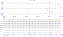
Pictures or numbers please,
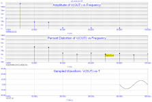
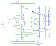
Pictures with numbers, please compare with my previous sim.
Attachments
So "effects to subtle to be modelled at all": if my sims only correspond so-so with the measured performance, I certainly would not put my money on sims bringing out the sort of subtleties we can percieve as human beings.
Let me put it in another way. Sims are based on a solid understanding of the basic interactions between the different electronic components. State of the art. And however advanced, while keeping within that mathematical model, you will never be able to enhance the state of the art. Sims by definition force you into that. Gödel all over again.
So, the only thing that works is theory, experimentation and measurement, adaptation of theory if needed, full cycle and ready to go again. This discussion has been a little short on experimentation and measurement.
IMHO, typical sims are useful for very-very limited tasks, like basic low-frequency linearity. They give support for very small initial step towards a final result - good sound. Many people even skip this first step, since basic linearity below 1% THD can easily be reached without sims.
All other effects, important for sound, do not sit in sims models, like, EMF interactions, vibro-electrical effects in capacitors, PCB design effects, and many other things, that John Curl is trying to bring onto the surface.
At the same time, sims have definitely more importance for OP Amps design, since in this case the mentioned as an example EMF and lytics effects are out of game.

Hi,
How about 19 & 20KHz Results, as well 76 & 80Khz...?
Ciao T
My results of JC3 sim. With 1Meg resistors Vout is lower, but harmonics higher. Qiuite logical results
How about 19 & 20KHz Results, as well 76 & 80Khz...?
Ciao T
- Status
- Not open for further replies.
- Home
- Member Areas
- The Lounge
- John Curl's Blowtorch preamplifier part II