Lasy Cat i modify the pcb based on your advice.
Marc
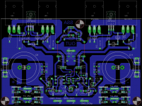
OK Marc, fine but to mine opinion you could left fuses on previous PCB positions, it looked nicer before, just to perform a little copper connections adaptation. To have PCB in max symmetrical look you could also move single wire jumper to the middle position, otherwise very neat to the eye.
")
Last edited:
Fuses are normally used to prevent fires, through prolonged fault conditions. In that case placing the fuse in the AC path as LC recommends is valid. This means the fuse will blow in the event of devices going faulty and the board/wiring starts to burn. A fuse should always be used when changing from a large wire dimension to a smaller wire dimension.
Fusing of the incoming mains to the transformer is normally sufficient and if it blows you do not have a possibility that a faulty component swings the output to one rail and remains there.
Hello Nico, nice to see you again. I always like to see way of clarifying things of oldschools.
By the way, it bothers me a bit to see fuse holders on those pcbs. As I mentioned before, pcbs should be without power unit on board in my opinion. This is a very early stage of an implementation and people may use just one PS unit for each pcb/circuit experimentation.
Cheers.
Last edited:
What do you mine by looks nicer? Juste aesthetetical?
Marc
Yes, just aesthetetical.
Leave the fuses on previous physical positions and wire them like it is on your last schematic, it would take only a split second of your time, regards Andrej.

Last edited:
By the way, it bothers me to see fuse holders on that pcbs everytime. As I mentioned before, pcbs should be without power unit on board. Because this is very early stage of an implementation and people may use just one PS unit for each pcb/circuit experimentation.
Cheers.
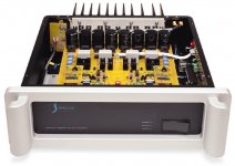
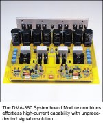
People who design PCB's on their own usually make them functional to their exact needs-wishes, I don't see any reason why not. To have PSU on PCB also means less wires (spaghetti) present in an amp's case. In according to high speed design like SSA is, where all AC paths are concluded in a very short loop, it makes a lot of sense too. Please look how high speed amps like Spectral are built (PCB, heatsink, etc.).
Attachments
As an adept of curent feedback for audio from 20years, now, (i run a Mak Alexander like amp) i'm happy to see this project.
Definitively, i think current feedback makes the best sounding low IM amps or preamps.
I have some questions about this design.
Why don't you use a Fet input Op amp to get rid of thermal/appairement of the input devices ?
For the versions with transistor for thermal compensation/quiescent current, why not use a FET instead of NPN (problems of stability with NPNs in such stages on edges of positive signals).
Did somebody knows this design, not so far from SSA and yet available as a kit:
http://www.ebay.co.uk/itm/2-X-DELUXE...item230a47af0e
(If somebody can make a simulation, i would really like to read the results)
Dumb questio I will go for IRF610,sorryone question from rather lazy, can I put FQP4N20/FQP7P06 or FQP4n20/IRF9610 which I have in stock or go to the shop for IRF610? Thanks


Okay, so who built what so far and what feed back can you provide the other enthusiasts.
Nico
Hi Nico
I think there will be some SSA versions pop-up soon, PCB's were presented, so it is only a question of time when they'll appear. After sonics confirmations of our's claims there will be still some more ...

Nico It would be also very nice to put some pic of yours SSA ... please, I'm very curious.

Why don't you use a Fet input Op amp to get rid of thermal/appairement of the input devices ?
Because than it would be just another copy of the Fets.
... why not use a FET instead of NPN (problems of stability with NPNs in such stages on edges of positive signals).
Because there is no instability issue noticed whatsoever.
LC,
Could you please email me? I have a circuit to send to you!
Hugh
PM sent.
Thanks, Andrej
- Status
- This old topic is closed. If you want to reopen this topic, contact a moderator using the "Report Post" button.
- Home
- Amplifiers
- Solid State
- Simple Symetrical Amplifier