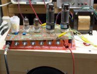
Hi Daryl, I should have used the word 'breadboard', not 'prototype'.I hope those exposed primary taps on the output transformer are going to be shrouded.
That arrangement is what I used to develop my 6AK5 preamps on previously, and I just took out a tube socket and screwed on the PA tfmr. My plan for the 'Lord of the Rings' is to have all the trfmrs inside and only the tubes poking thro the top. Sockets and switches and knobs along one side.
Cheers
Hi Printer2,
glad you bounced - I am an ex motorcyclist and can feel your rash.
Love your switching options, I did take your pp to self split switch for my amp on yesterday's post.
This thread has been great for sharing ideas.
Keeping the volume and the complexity down (switches don't count) has been as much a challenge as the $100.
Cheers
Last edited:
something is weird around your source follower. It does not have a gate bias,
The source follower will work fine if you remove the .022 cap on the gate and replace it with a short. It is the same design I use, and tonight I decided to turn up the fun. Since I already know how violently the electrolytics that I am using explode on 600 volts, I decided to stay within the ratings. I set the power supply on 450 volts for my 450 volt caps.
 So far the only thing I blew up is a resistor. It was the stinkyest resistor I ever fried. I did the proper Tubelab thing and just put in a bigger resistor.
 I am making an amp design that can be built for several prices. Some will fit this budget, and some will not. It is all a matter of what parts you stuff into the board, and what tubes you use. SO.....since there has been some talk about violating the rules a bit, I decided to wire in a real OPT, connect up a variable power supply, and roll some tubes through this thing. NO other changes were made.
The budget consious choice is 6BQ7/6BZ7/6BK7 in all 3 preamp sockets and 6EZ5's or 6W6's in the output sockets. 6BQ7's are $3 each and 6EZ5 were on the $1 list but are $4 now. The 6W6 is $3. The fun starts at 250 volts on the B+ and it rocks at 350 or maybe....just a bit more. Power is 10 to 20 watts depending on supply voltage. If a reasonable OPT and an Antek 05T230 is used for the power transformer it will fit into the under $100 budget.
A 12V6 tube is $3 and it fits the budget and sounds real good. This allows 12 volt dual triodes too. Of course you can bust the budget and use 12AX7's but there is actually too much gain. There are several other possibilities.
I rolled about 50 tubes through this thing. I know what's going into my amp, but the tubes cost more than the rest of the amp! When I was experimenting with the series string heaters I tried 26AQ8/UCC85 tubes. So for the 6 volt version I plugged in some ECC85's they ROCK but cost $15 EACH! Of course to get that Marshall cranked to 11 sound you got to stuff the amp with EL34's and set the power supply for 450 volts. I got my Sovteks for $10 each but I guess they cost more than that now.
Attachments
Shoot, threw in the MOSFET and forgot to remove the capacitor.Hi Printer2;
something is weird around your source follower. It does not have a gate bias, and I think B+ voltage to power it is too high.
Also, I suggest you to utilise screen grid current to add some sagging through B+ for preamp.
Hi Printer2,
glad you bounced - I am an ex motorcyclist and can feel your rash.
Love your switching options, I did take your pp to self split switch for my amp on yesterday's post.
This thread has been great for sharing ideas.
Keeping the volume and the complexity down (switches don't count) has been as much a challenge as the $100.
Cheers
Good someone has use for the split to p-p idea. I wanted to use it but in the end I saw another shiny object. I might go back to it after I see if I can get this working.
Not sure if I mentioned it before but the same circuit can be used for self split, push pull, for a SE amp using the same board. Just a part or jumper change, in the case of the SE amp a different OT but even that could be worked around by biasing the bottom p-p tube constantly on. What I wanted to do is not give a specific design but rather a platform to play with. I also wanted to see what a 70V transformer can do in p-p and in SE, I already converted one with an air gap.
Hopefully tomorrow I will get some more construction done. It was a bit too awkward today so I spent the time doing the schematic. Not sure if the MOSFET is necessary, I am not looking to make a gain monster, but I will leave space for it. Also the idea for this amp is to put a booster in front of the amp to drive the pentode harder if need be.
When you finalize the design are you thinking about offering boards or kits?
A lot depends on the attitude of my wife when she finally returns home. She has been away for over a year, and on and off before that caring for her mom. Since I was there for the funeral another relative had died, and a third in in the hospital with cancer.
Sherri has been under a lot of stress due to all this BS, but she seems to be in favor of closing Tubelab Inc. down since it consumes a lot of time and doesn't make any money. With the crummy economy board sales are very slow now.
It's too soon to tell, but I would like to do boards for the most popular designs.
Not sure if the MOSFET is necessary, I am not looking to make a gain monster, but I will leave space for it.
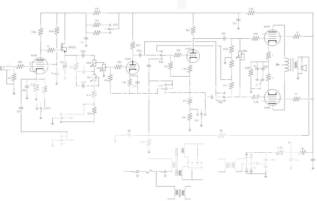
I included mosfet buffers for the output of every stage in the first pass PC board. The amp currently has 2 mosfets. One drives the volume control, and I am not sure it really does much. I am going to try a 1 Meg volume control without the mosfet and see if it cuts too much treble or loses gain.
The mosfet feeding the tone stack is a keeper. Simulation of the tone stack shows it is better behaved with a low source impedance. Testing with and without the mosfet confirms this. I use a 47 K 1 watt resistor for the source to ground resistor and an LND150 mosfet in the TO92 package. It is the cheapest HV mosfet in the Mouser catalog and works fine.
A gate stopper resistor is needed to keep my design from oscillating at 24 MHz but I am using VHF TV tuner tubes. I am using a 27 K resistor where your coupling cap is.
Gate stopper, glad you mentioned it, another thing I overlooked. I also see that I did not do a complete voltage doubler, did a bunch of cut and pastes from different designs and missed a few things. I also found the software I have actually does have a Mosfet symbol, I did not have to use the J-Fet.I included mosfet buffers for the output of every stage in the first pass PC board. The amp currently has 2 mosfets. One drives the volume control, and I am not sure it really does much. I am going to try a 1 Meg volume control without the mosfet and see if it cuts too much treble or loses gain.
The mosfet feeding the tone stack is a keeper. Simulation of the tone stack shows it is better behaved with a low source impedance. Testing with and without the mosfet confirms this. I use a 47 K 1 watt resistor for the source to ground resistor and an LND150 mosfet in the TO92 package. It is the cheapest HV mosfet in the Mouser catalog and works fine.
A gate stopper resistor is needed to keep my design from oscillating at 24 MHz but I am using VHF TV tuner tubes. I am using a 27 K resistor where your coupling cap is.
I will be using a IRF820 rather than a LND150 as you can get them or a replacement all over, even EB*y while as I had a hard time finding the LND150 anywhere other than Mouser for a reasonable price. Picked up a bunch from Mouser but shipping would have been too much if I only bought a couple of parts. Originally I would have gone with the LND150 as the first stage but semi's are not allowed for gain stages.
Might go for a dual pot on the post PI volume control, you can pick them up online for about what a single costs. Not sure if it is necessary though.
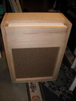
It looks like I'll be completing the amp after all. I started on the cab today, and had to stop to make a drilling jig for the dowels. Cab is assembled with two dowels on each end of each horizontal section, except the miter cut 3/4" frame around the speaker board.
There is an additional horizontal brace across the back bottom making a tub for the Reverb Tank.
There is an additional horizontal brace across the back bottom making a tub for the Reverb Tank.
Attachments
I took my two 12 inch cabinets outside this afternoon for a meeting with the belt sander. It was 95 degrees with 90% humudity, so the session didn't last long.
I was hpoing to have them ready for covering this weekend, but the cabinets are delayed for another week. The little 8 inch Jensen was eating whatever a pair of EL34's on 450 volts put out for about an hour last night. That amp will be potentially lethat through 2 X 12 inch speakers.
I was hpoing to have them ready for covering this weekend, but the cabinets are delayed for another week. The little 8 inch Jensen was eating whatever a pair of EL34's on 450 volts put out for about an hour last night. That amp will be potentially lethat through 2 X 12 inch speakers.
The cab will be uncoverd, Red Oak. I plan on building it with Tremelo, and Reverb, although the Rerb can be left out to meet the $100 limit.
I'm still up in the air as to which speaker to use. I have a couple Magnavox 12" speakers that sound pretty good and might be a better choice over the Blue Marvel which I'm currently running. I could make several speaker boards and switch them out. I've got grill cloth on order.
I'm still up in the air as to which speaker to use. I have a couple Magnavox 12" speakers that sound pretty good and might be a better choice over the Blue Marvel which I'm currently running. I could make several speaker boards and switch them out. I've got grill cloth on order.
I have been conducting my experiments so far using a "real" OPT designed for a guitar amp and rated for 80 watts. I have cranked 150 watts through these and currently use a pair on my "red board" HiFi amp at 125 WPC. Even though I got them real cheap they are not common any more and thus don't qualify for this challenge.
I have purchased nearly $200 worth of iron that I thought worthy of being repurposed as an OPT. Many of my guesses just sucked. Some worked but costs some power output. A few are still other contenders for other designs.
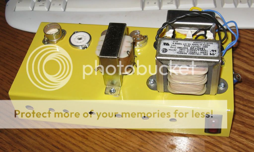
Tonight I found a $13 transformer that kicks out 20 watts. It has under 1% distortion at 10 watts and 1KHz, measured from the PI input to the speaker out. At 15 watts the power is down 0.15 db at 80 Hz and saturation distortion distortion does not show up until 50 Hz (don't use it for bass guitar at this power level. The upper 3db point at 15 watts is 17 kHz.
What is it? It is an Antek power toroid rated at 50VA. I am using the 9 volt version with both secondaries in parallel. Part # AN-0509. Other tube / voltage combinations might need a different ratio. I will look no further for this amp. OH, is sounds good to, bass is as solid as it can be through an 8 inch speaker and the distortion at full crank through the bridge pickup is ear piercing...in a good way. Total iron cost for a 20 watt guitar amp is $34.
I also removed a gain stage from the signal path. It still has plenty of gain and the touch sensitivity seems to have improved while the amp has become much more stable and civilized.
I have purchased nearly $200 worth of iron that I thought worthy of being repurposed as an OPT. Many of my guesses just sucked. Some worked but costs some power output. A few are still other contenders for other designs.
Tonight I found a $13 transformer that kicks out 20 watts. It has under 1% distortion at 10 watts and 1KHz, measured from the PI input to the speaker out. At 15 watts the power is down 0.15 db at 80 Hz and saturation distortion distortion does not show up until 50 Hz (don't use it for bass guitar at this power level. The upper 3db point at 15 watts is 17 kHz.
What is it? It is an Antek power toroid rated at 50VA. I am using the 9 volt version with both secondaries in parallel. Part # AN-0509. Other tube / voltage combinations might need a different ratio. I will look no further for this amp. OH, is sounds good to, bass is as solid as it can be through an 8 inch speaker and the distortion at full crank through the bridge pickup is ear piercing...in a good way. Total iron cost for a 20 watt guitar amp is $34.
I also removed a gain stage from the signal path. It still has plenty of gain and the touch sensitivity seems to have improved while the amp has become much more stable and civilized.
Attachments
Last edited:
I saw in the July 28 issue of EDN an ad by Triad Magnetics for Toroidal transformers from 25VA to 2.5KVA.
I suspect they will be quite a bit more in costly than An-Tek, but it looks like the market is growing for them.
They are specifying UL Class B with 4KV isolation primary to secondary. 115/230 split primary 50/60Hz, and secondaries from 6 to 230V.
http://www.triadmagnetics.com/pdf/Triad_VPTSeriesNews%20Jan2011.pdf
FOund them at Newark, $29.86 for a 50VA transformer! Yikes.
Last edited:
I saw in the July 28 issue of EDN an ad by Triad Magnetics for Toroidal transformers from 25VA to 2.5KVA.
I suspect they will be quite a bit more in costly than An-Tek, but it looks like the market is growing for them.
They are specifying UL Class B with 4KV isolation primary to secondary. 115/230 split primary 50/60Hz, and secondaries from 6 to 230V.
http://www.triadmagnetics.com/pdf/Triad_VPTSeriesNews%20Jan2011.pdf
FOund them at Newark, $29.86 for a 50VA transformer! Yikes.
How do you guys go about estimating the pri/sec inductances for these transformers? The spec sheets only have voltages shown...
Jaz
I also removed a gain stage from the signal path. It still has plenty of gain and the touch sensitivity seems to have improved while the amp has become much more stable and civilized.
Tonight I removed yet another gain stage from the lineup. So now there are two triode amp stages followed by an LTP PI and a push pull amp made with tubes that are a cousin of the EL84. The amp rocks and could be built with 4 tubes, but I prefer a bit more gain. I can still get some nice distorted tone, but I have to turn it up LOUD. Before I could crank the input gain, back off the master and get good distortion at low volume.
So 4 gain stages in front of the PI was too much. Microphonics and oscillation were a problem. 3 gain stages was good, I like a lot of gain for flexibility. 2 may not be quite enough. The gain stages come packaged 2 to a piece of glass, so its 2 or 4 stages. It is possible to cut one in half. In fact there is 1/2 of a 12AX7 in a single piece of glass that fits my series heater scheme. Don't know how microphonic they are though. More experiments are coming.
How do you guys go about estimating the pri/sec inductances for these transformers?
If you are indeed talking about inductance, the only way to find out if the toroid in question has enough inductance is to hook it up and measure the low frequency response and test for saturation IN THE CIRCUIT you intend to use. For a guitar amp, you want full power down to 80 Hz. Generally get a transformer that has a VA rating just a bit bigger than the expected power output in watts. The bigger transformers often don't have enough inductance to handle heavy bass. I have found exceptions though. I got a 50VA transformer because my amp puts out over 25 watts at full crank.
The impedance is a bit easier to figure out. You need to know the impedance that your tubes want to see. Lets just use 6600 ohms for this example because that is what I am using. You also need to know the speaker impedance. I am using 8 ohms.
Next we need to figure the turns ratio. The turns ratio is the square root of the impedance ratio. The impedance ratio is 6600 divided by 8 which is 825. The turns ratio is the square root of that. SQRT of 825 is 28.73.
We are using transformers that have dual 120 volt primaries wired in series for 240 volts. The voltage ratio is the same as the turns ratio so we simply divide 240 by the voltage ratio to get the desired secondary voltage. So 240 divided by 28.73 is 8.35 volts.
We choose a secondary as close as we can get to 8.35 volts. With dual secondaries you can series or parallel them to get the desired voltage. I chose a transformer with two 9 volt secondaries wired in parallel. It works great.
FOund them at Newark, $29.86 for a 50VA transformer! Yikes.
I saw them somewhere too, maybe Allied, but they were too expensive.
Last edited:
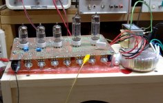
So, I've made the final (GU50 single ended) stage of the prototype and hooked it up to the power supply. It looks like that.
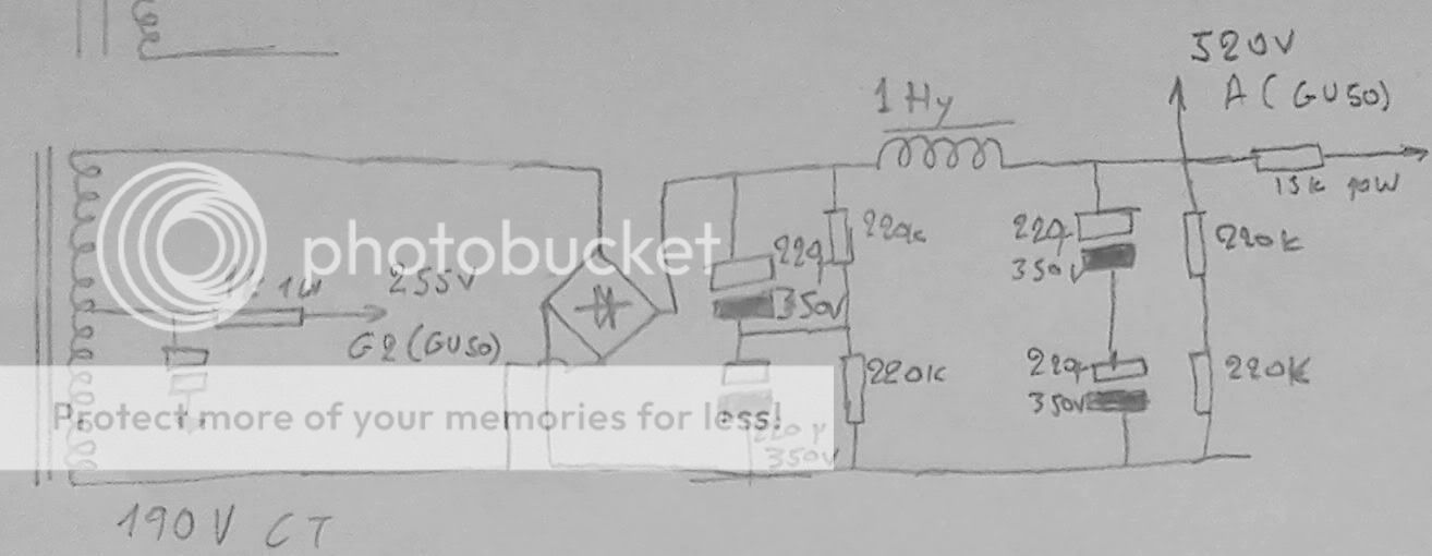
The issue is that since there is ~25V cathode bias, the G2 voltage is a little low, it may be 255 V from G2 to ground, but the cathode bias is stealing from that. So I get pretty low G2 current (~1.2 mA) and power output is low-ish, and also because of the G2 resistor being only 1 kilohm , I get very little compression.
So I am going to do this
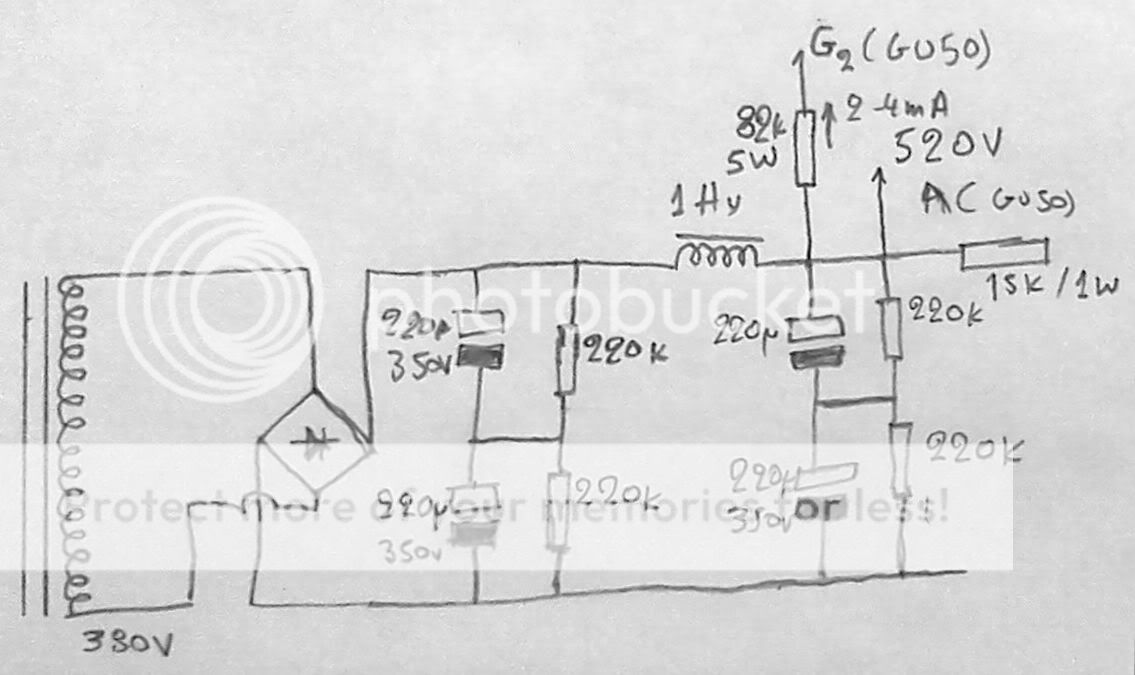
The G2 resistor is going to be carbon comp 1W, and will be adjusted on test. cold be anything from 56 to 120K. This will give me compression too.
So, does it look OK to you, guys? Maybe there is another way to do it better? (no sand please!). Maybe I should "split" the G2 feed resistor in 2 and have a capacitor in the middle, to have less compression?
Another question: My "customer" (read victim ) is asking about GU50 longevity in this amp. It is running around 85mA, 480V cathode to plate. What do I tell him?
The issue is that since there is ~25V cathode bias, the G2 voltage is a little low, it may be 255 V from G2 to ground, but the cathode bias is stealing from that. So I get pretty low G2 current (~1.2 mA) and power output is low-ish, and also because of the G2 resistor being only 1 kilohm , I get very little compression.
So I am going to do this
The G2 resistor is going to be carbon comp 1W, and will be adjusted on test. cold be anything from 56 to 120K. This will give me compression too.
So, does it look OK to you, guys? Maybe there is another way to do it better? (no sand please!). Maybe I should "split" the G2 feed resistor in 2 and have a capacitor in the middle, to have less compression?
Another question: My "customer" (read victim
) is asking about GU50 longevity in this amp. It is running around 85mA, 480V cathode to plate. What do I tell him?i asked this question somewhere else, but is it possible ot omit the output transformer on a small single ended amp and connect a dpeaker direct to the tube output via a 500 or more ohm resistor?
this would make the build much cheaper and allows for a bit more to be spent on perhaps a better isolating/power transformer and/or tube rectification if you should want it....
thanks in advance
this would make the build much cheaper and allows for a bit more to be spent on perhaps a better isolating/power transformer and/or tube rectification if you should want it....
thanks in advance
This is a thread on building cheap guitar amps. However, if you go through it, ALL amps have output transformersi asked this question somewhere else, but is it possible ot omit the output transformer on a small single ended amp and connect a dpeaker direct to the tube output via a 500 or more ohm resistor?
this would make the build much cheaper and allows for a bit more to be spent on perhaps a better isolating/power transformer and/or tube rectification if you should want it....
thanks in advance
- Home
- Live Sound
- Instruments and Amps
- The Hundred-Buck Amp Challenge