Could separate supply rails be used to obtain higher rail voltages for the output stage?
Yes it could, but then you would need a CFP output stage with local feedback for voltage gain. The circuit in my previous post does exactly that.
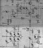
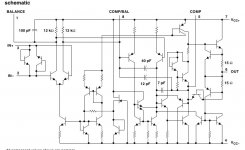
Here is the rest of the circuit, showing how to derive the lower op-amp supply voltage from the rail voltage. Apologies for the poor quality of the scan.

All of the additional components for dropping voltages and adding feedback makes the circuit more complicated than suggested by the heading for this thread.
Attachments
Last edited:
Another answer on tiefbassuebertr's question on where the current goes. Here is another op-amp based power amp that does it exactly the same. There seem to be nowhere for the diode current to go but into the op-amp's output!
Found it on the Elliot Sound Products website:
Opamp Based Power Amp
Can somebody shed some light on this little mystery?
PS: the above topology is ideally suited to the NJL1302/NJL3281 mentioned above. Watch this space.
An externally hosted image should be here but it was not working when we last tested it.
Found it on the Elliot Sound Products website:
Opamp Based Power Amp
Can somebody shed some light on this little mystery?
PS: the above topology is ideally suited to the NJL1302/NJL3281 mentioned above. Watch this space.
Last edited:
Can somebody shed some light on this little mystery?
There is none ...

Having an op-amp that sinks current is not a problem as long as you stay within the limits. In this case the current is about 5mA which should be OK.
Right , but when the op amp output is in full negative swing ,
the current will double from about 6mA to 12mA,
not counting that the negative side has better
current capability than the positive side.
Also, R6 seems quite high , its value should be at most
one or two kilo ohm..
Overall, the design is lacking.
Last edited:
Needs a VAS, badly!!!
Inserting a VAS is not that trivial.
Stability would be way more problematic.
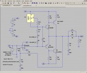
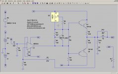
Here is another variation, using Thermaltrak output devices.The power output is up, but so are the prices of the components. The first circuit was really cheap and cheerful, with the op-amp and output trannies just over US$1 each. Now we are looking at US$7 each. The circuit is however free of anything to adjust.
It looks pretty good in LTspice, maybe a little too good to be true. THD for 40W into 8 ohm (1kHz) is 0,0009%. Output into 4 ohm is 70W and for 2ohm it is 100W. There seems to be no need for any compensation.
The circuit will work without R11 or it can be replaced with a pot, as the THD depends on it. Without it the THD (measured as above) goes up to 0,007%. Too large a value and you have a class A amp on your hands. It seems quite sensitive to variation. At 56 ohm it's already in class A.
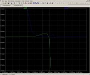
This is one of those times where simulation shows its limitations. Only real world measurements will tell us what we want to know. Perhaps R11 is best left out. The collector currents below shows the switching distortion that accounts for the difference in THD. On the other hand, measuring this sort of thing in the real world and making adjustments to get the very best possible THD probably requires equipment that few amateurs have.
How true all of this is depends in large part on the accuracy of the SPICE models. The transistor models came from Cordell Audio and the op-amp model is from Texas Instruments. It is therefore as good as it gets. The proof of the pudding is, as always, in the eating. Time to go shopping for components.
It looks pretty good in LTspice, maybe a little too good to be true. THD for 40W into 8 ohm (1kHz) is 0,0009%. Output into 4 ohm is 70W and for 2ohm it is 100W. There seems to be no need for any compensation.
The circuit will work without R11 or it can be replaced with a pot, as the THD depends on it. Without it the THD (measured as above) goes up to 0,007%. Too large a value and you have a class A amp on your hands. It seems quite sensitive to variation. At 56 ohm it's already in class A.
This is one of those times where simulation shows its limitations. Only real world measurements will tell us what we want to know. Perhaps R11 is best left out. The collector currents below shows the switching distortion that accounts for the difference in THD. On the other hand, measuring this sort of thing in the real world and making adjustments to get the very best possible THD probably requires equipment that few amateurs have.
How true all of this is depends in large part on the accuracy of the SPICE models. The transistor models came from Cordell Audio and the op-amp model is from Texas Instruments. It is therefore as good as it gets. The proof of the pudding is, as always, in the eating. Time to go shopping for components.
Attachments
Last edited:
Needs a VAS, badly!!!
Perhaps, but then it will be just another three stage Lin design. I want to see with just how few components you can build a decent amp. Ultimate performance is not important. I want something that is simple, cheap and easy to build. And I want something that I understand. Otherwise it goes like this:
An externally hosted image should be here but it was not working when we last tested it.
"Yes, that is the latest thing in audio technology. It works very well. What goes on inside it is a really complicated complicated trade secret and uhm, er....."
This circuit is close by those circuit, that was published in the german magazine "ELRAD" - go to post 13 aboutHere is a very simple amp schematic that has excellent performance that I published here some five years ago.
Nico
http://www.diyaudio.com/forums/solid-state/99967-anybody-have-scan-483b-motorola-2.html#post2671320
to download pdf file.
Also this thread could be of intetesrt in this case:
http://www.diyaudio.com/forums/solid-state/165165-edwin-20-watt-elektor-1970-may.html
What means "I published here" ??
Here on diyaudio?
Or mean you an electronic magazine in your country?
Independent of this - can you give some advices about vintage and currently available electronic magazines from your country about
http://www.diyaudio.com/forums/soli...ble-electr-audio-magazines-2.html#post2671316
Thank you very much therefore.
Here is a very simple amp schematic that has excellent performance that I published here some five years ago.
Nico
What is the value of X1?
What is the value of X1?
Such that it makes with R49 a divisor with about a 2 ratio.
So R49 value is rather 220K , and same for X1.
Such that it makes with R49 a divisor with about a 2 ratio.
So R49 value is rather 220K , and same for X1.
Wahaabb... my friend.. glad to see you agaiinn
Wahaabb... my friend.. glad to see you agaiinn
Hi , Tomat,
Good to see you by there.
Did your hybrid feedbackless amp finally become reasonnable ?..
Hi , Tomat,
Good to see you by there.
Did your hybrid feedbackless amp finally become reasonnable ?..
yess.. i still enjoy it till now.. and that because your help too
many thanks my friendyess.. i still enjoy it till now.. and that because your help too
That s great , running all that time means it is very reliable..
Last edited:
Here is a very simple amp schematic that has excellent performance that I published here some five years ago.
Nico
This is probably more in keeping with the title of this thread. Perhaps I should have titled it "Class B amp with low component count." Then again, the internals of the NE5534 and LM334 are not that simple and they have lots of components.
Attachments
Member
Joined 2009
Paid Member
Ingenious,
It's not clear that this offers lower parts count but thought you may like to read the article. Scroll down to the section with the title "Class B amplifier has automatic bias"
http://www.edn.com/contents/images/6702272.pdf
It's not clear that this offers lower parts count but thought you may like to read the article. Scroll down to the section with the title "Class B amplifier has automatic bias"
http://www.edn.com/contents/images/6702272.pdf
Ingenious,
It's not clear that this offers lower parts count but thought you may like to read the article. Scroll down to the section with the title "Class B amplifier has automatic bias"
Thanks. It look very interesting. The example given is for a headphone amp but the design should scale up well.
Automatic bias is something I have tried a few years ago. All I could prove then was that it is easy to fry transistors. This one makes me feel like getting back on that horse again.
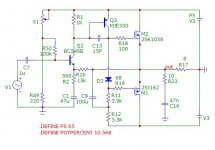
I have had another look at the circuit in post one. It seems that the constant current delivered by the LM334 means that the resistors values for the Vbe multiplier can vary quite a lot while the circuit keeps working. There is an optimum setup that gives the lowest THD of course, but if one is willing to live with a compromise it should be possible to spec values that will work. This means that the dreaded pot is no longer needed.
Of course this has to be verified by building an actual version. For the price of a Big Mac in components(*) how can one resist?
You will also notice that I have tweaked the frequency response a bit, and made the symbols look a bit nicer.
(*) Excluding power supply, heat sink, PCB, cabinet e.a.
Attachments
- Status
- This old topic is closed. If you want to reopen this topic, contact a moderator using the "Report Post" button.
- Home
- Amplifiers
- Solid State
- Very simple class B amplifier