OK thanks AJ, corrected.")
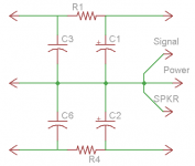
Not quite Lazy Cat. Sorry if my post wasn't clear. I would have posted a sketch and a reference but I was at work. This method is from Bob Cordells recent book, pg.351. His supply is little more complicated using double the electrolytics, but applying it to your PS you'd have something like the attached diagram.
The main point of this method is it gets the main star connection away from the high currents flowing between the filter caps, giving a better, cleaner gnd reference point. Like I said minor change to your diagram, but it makes a big difference when it comes to laying out a PCB.
Attachments
Lazy Cat, Nico,
Brilliant, off the wall contribution..... a great amp!!
I particularly like the mosfet/bipolar output stage, it inserts a EF output which is always preferable for difficult loads (ie speakers!).
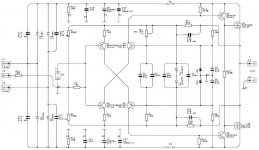
At the cost of adding some distortion, you could slightly increase one of the 10R CCS resistors (R3 or R4 in the above schemat) to 12R to deliberately drive the harmonic profile towards even artefacts; this would 'warm' it up a little.
Cheers,
Hugh
Brilliant, off the wall contribution..... a great amp!!
I particularly like the mosfet/bipolar output stage, it inserts a EF output which is always preferable for difficult loads (ie speakers!).
At the cost of adding some distortion, you could slightly increase one of the 10R CCS resistors (R3 or R4 in the above schemat) to 12R to deliberately drive the harmonic profile towards even artefacts; this would 'warm' it up a little.
Cheers,
Hugh
Not quite Lazy Cat. Sorry if my post wasn't clear. I would have posted a sketch and a reference but I was at work. This method is from Bob Cordells recent book, pg.351. His supply is little more complicated using double the electrolytics, but applying it to your PS you'd have something like the attached diagram.
The main point of this method is it gets the main star connection away from the high currents flowing between the filter caps, giving a better, cleaner gnd reference point. Like I said minor change to your diagram, but it makes a big difference when it comes to laying out a PCB.
Yeah the GND point, it certainly should be the zero-reference potential for the load and the unbalanced input since we try to make a comparison between them, differing only in a gain factor. It is logical that the messy ripple current flowing near smoothing capacitors should not interfere with any of them especially with the input bias current since these two are like David and Goliath. So the distance preventing the last modulate the weak one is reasonable solution.
Thanks to point out this again to clarify the problem, appreciate it, will be considered at PCB designing process.
Attachments
Lazy Cat, Nico,
Brilliant, off the wall contribution..... a great amp!!
Thanks a lot Hugh, I am honoured with your presence, it positively influences the project.
I particularly like the mosfet/bipolar output stage, it inserts a EF output which is always preferable for difficult loads (ie speakers!).
I share the same thoughts as you are. BIGBT even has EF&CF combined in a parallel manner, equally loading the mosfet driver.
At the cost of adding some distortion, you could slightly increase one of the 10R CCS resistors (R3 or R4 in the above schemat) to 12R to deliberately drive the harmonic profile towards even artefacts; this would 'warm' it up a little.
Cheers,
Hugh
Will try that soon in sim to see the change in a harmonic distortion profile result. Thanks for the tip, Cheers.
Hi AlexMM,
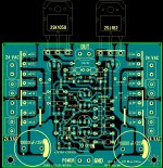
Very nice & compact PCB. I may build this to compare to my Goldmund clone.
The connectors for the 24V AC seems to take up a lot of real estate. I suggest to use only one terminal connector & two quik-on for each rail.
The max diameter for the 10000uF filter cap is only 20mm, that will limit the choice. I suggest to move the filter caps by 3mm so that we can install caps up to 25mm diameter.
Cheers, Stanley
Attachments
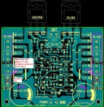
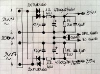
The power rails into the Lat FETs come from the rectifier end of the PSU.
The rectifier must feed the smoothing capacitors and then the capacitors must feed the amplifier.
Doing it your way mixes the charging pulses with the audio current in the shared traces around the rectifier/smoothing. There is a high risk of Buzz getting into the output.
The rectifier must feed the smoothing capacitors and then the capacitors must feed the amplifier.
Doing it your way mixes the charging pulses with the audio current in the shared traces around the rectifier/smoothing. There is a high risk of Buzz getting into the output.
I agree, nice compact PCB, but I don't think it is a good idea to have AC cables near Mosfet pins, apart the fact that some of us like to apply all kind of tricks to the power supply, like -ECdesigns-' smooth stepped rectification, "charge transfer supply" or even V regulation...
Good luck and thanks for sharing.
M.
Good luck and thanks for sharing.
M.
View attachment 234829
Hi Alex,
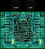
Version 1.1 look better than 1.0, good work.
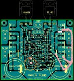
I agree with Andrew that the routing of the power rails can be improved. I have highlighted one possible routing in pink.
I also suggest that the 24V AC quik-on can be moved a bit closer so that their holes are 5mm apart. People can use screw-on terminal connector with 5mm lead spacing if they wish to.
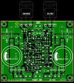
I did a quick check with the layout, the routing are spot-on.
ZD1 should be ZD2 & vice versa; the polarity of the zeners & the 47uF capacitors are reversed.
Cheers, Stanley
AndrewT[ATTACH said:234829[/ATTACH];2668016]The power rails into the Lat FETs come from the rectifier end of the PSU.
The rectifier must feed the smoothing capacitors and then the capacitors must feed the amplifier.
Doing it your way mixes the charging pulses with the audio current in the shared traces around the rectifier/smoothing. There is a high risk of Buzz getting into the output.
Hi Alex,
Version 1.1 look better than 1.0, good work.
I agree with Andrew that the routing of the power rails can be improved. I have highlighted one possible routing in pink.
I also suggest that the 24V AC quik-on can be moved a bit closer so that their holes are 5mm apart. People can use screw-on terminal connector with 5mm lead spacing if they wish to.
I did a quick check with the layout, the routing are spot-on.
ZD1 should be ZD2 & vice versa; the polarity of the zeners & the 47uF capacitors are reversed.
Cheers, Stanley
Attachments
Last edited:
Simulation.....
I have simulated the circuit shown in #141 from Lazy Cat. I had to decrease R13 to 7.5 ohms (from 330 ohms) to get the no signal bias current to under 200ma. I guess my models of the lateral fets ALF16N20W and ALF16P20W have pretty low Vgs requirements. Each is around .5 volts Vgs for less than 200ma. The Cordell models of the 2SK1058/2SJ162 worked about the same in this circuit, no signal. Initially I was getting 54A, no signal. Still, I checked the FET datasheet and .5 volts Vgs is about right for this current. I like the ALF16N/P20W because those parts are easy to obtain, cheap here in the US and the fact that they are 16A parts.
Overall, still a well behaved amp and very wideband. But, IMHO, it IS an experimental design. Has anybody shorted out the REAL output to see if it survives? Many designs, like this one, on this and other forums have all SC and SOA protections omitted for many reasons, usually sonic.
Hi Michael,
I agree with decoupling the front end from the power end. I have learnt a trick from Hugh to simply decouple it with a diode and capacitor that way the front end supply remains very stable, regardless of sag caused by the power stage. Sag is usually pretty brief and only occurs during heavy current passages.
Regards
Nico
- Status
- This old topic is closed. If you want to reopen this topic, contact a moderator using the "Report Post" button.
- Home
- Amplifiers
- Solid State
- Simple Symetrical Amplifier