No, I did a research on the 'popularity' of the term: 'slew rate' in the 1960's, based on my books and company product binders from the '60's. Slew rate was rarely mentioned, except in some IC op amps. There was a good reason for this, we just did not follow the OP AMP model for amp design most of the time. I think the first real op amp example was the Crown DC-300.
Cherry and Hooper's book OMITTED any reference to dV/dT, Slew Rate, Slope distortion, or any other rate of change info in their almost 1000 page book on amplifier design.
Cherry and Hooper's book OMITTED any reference to dV/dT, Slew Rate, Slope distortion, or any other rate of change info in their almost 1000 page book on amplifier design.
Last edited:
http://www.analog.com/library/analogDialogue/bestof/pdf/01_3.pdf
1967 and most op-amps were discrete bricks or boards. This article clearly states the relationship between large signal frequency response, slew rate, and distortion.
1967 and most op-amps were discrete bricks or boards. This article clearly states the relationship between large signal frequency response, slew rate, and distortion.
http://www.analog.com/library/analogDialogue/bestof/pdf/01_3.pdf
1967 and most op-amps were discrete bricks or boards. This article clearly states the relationship between large signal frequency response, slew rate, and distortion.
Cool! Got any more of those, Scott?
se
As I mentioned, in the 1960's we normally did not make 'classic' op amps for audio reproduction, either for consumer or pro designs. We usually used as few solid state devices as possible, AC coupled, both input and output, usually consisting of 2 or 3 active devices with some sort of feedback loop around them. Push pull output was reserved for power outputs, either for pro line drivers, or for power amps. The open loop gain was just enough to make 'spec' and the open loop frequency response had to be fairly high, in order to give adequate ultrasonic frequency response. I don't remember having to measure the slew rate of any designs we did at Ampex at the time (late '60's) it was just not important enough. I'm sure that IF we had tried, we could have found some problems, but usually the circuits, much like tubes tend to do, rise-time limited, rather than slew rate limited.
Last edited:
Gee,
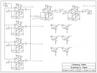
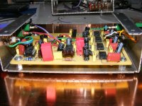
And I decided to build a high gain preamp using IC's. I paralleled four for the input stage, but when I checked one of then was noisy so I removed the resistor that added it to the mix. I had soldered all of the low level IC's to the board as I wanted to avoid possible socket noise issues. Noise values are shown.
Not narrowing of bandwidth as I did not want to look at LF and Flicker noise and too much HF is just as bad.
Attachments
Hello Scott,
You might not be watching :
http://www.diyaudio.com/forums/pass-labs/175040-more-fet-noise-measurements-euvl.html
Any news ? Sorry for hijacking.
Patrick
You might not be watching :
http://www.diyaudio.com/forums/pass-labs/175040-more-fet-noise-measurements-euvl.html
Any news ? Sorry for hijacking.
Patrick
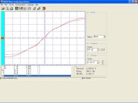
Well I soldered a jumper from the out put of the AP attenuator to the input of the preamp. I averaged 128 samples on my scope and then tried the same with a Sprague 1000/16 electrolytic (Large Axial Can) capacitor.
Anyone can interpret this however they want to. The curve with the lower peak is the signal after being passed through the capacitor.
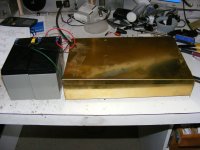
As a note the preamp is powered by batteries and the scope is feed through an isolation transformer.
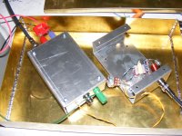
The sub chassis inside the big box are also isolated.
Anyone can interpret this however they want to. The curve with the lower peak is the signal after being passed through the capacitor.
As a note the preamp is powered by batteries and the scope is feed through an isolation transformer.
The sub chassis inside the big box are also isolated.
Attachments
Last edited:
Ed,
I hope the transformer was well shielded and use low distortion lams.
In my various test jigs I always place the transformer at the highest level and lowest impedance and attenuate after.
Transformers do pick up noise quite well...
Ciao T
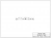
Well to drive the high gain preamp I needed a very small signal, so I just made an attenuator to take the output of my AP System 2 and drop the level and provide isolation. I also added a small LC (forgot to show the .01 C)
I hope the transformer was well shielded and use low distortion lams.
In my various test jigs I always place the transformer at the highest level and lowest impedance and attenuate after.
Transformers do pick up noise quite well...
Ciao T
Hi,
I interpret it as "both traces look like followers of the Caliph Ali", one seems to look a little worse and shows extra attenuation.
I'd like to see the result of a multitone test looped back into the AP2...
Ciao T
Well I soldered a jumper from the out put of the AP
attenuator to the input of the preamp. I averaged 128 samples on my scope and then tried the same with a Sprague 1000/16 electrolytic (Large Axial Can) capacitor.
Anyone can interpret this however they want to.
I interpret it as "both traces look like followers of the Caliph Ali", one seems to look a little worse and shows extra attenuation.
I'd like to see the result of a multitone test looped back into the AP2...
Ciao T
Cool! Got any more of those, Scott?
se
The entire series is in .pdf on our site for free download. We also have one of Walt's books online too, I think.
Hi,
I interpret it as "both traces look like followers of the Caliph Ali", one seems to look a little worse and shows extra attenuation.
I'd like to see the result of a multitone test looped back into the AP2...
Ciao T
Both traces do show issues. Keep in mind 1 volt on the scope is really a bit less than 1 uv.
The source resistance is 100 ohms so the noise from that should be around 100nv.
The level is well below the AP's resolution. I did check it after the transformer and if I find the data I will post it.
The transformer distortion is not showing up as a significant issue.
Well to drive the high gain preamp I needed a very small signal, so I just made an attenuator to take the output of my AP System 2 and drop the level and provide isolation. I also added a small LC (forgot to show the .01 C)
You have some real Wavy Gravy there Ed.
EVUL - Anything that requires a lot of bench work is on hold until my current project tapes out.
http://www.analog.com/library/analogDialogue/bestof/pdf/01_3.pdf
1967 and most op-amps were discrete bricks or boards. This article clearly states the relationship between large signal frequency response, slew rate, and distortion.
Good paper Scott, thanks.
What struck me is the style of drawing the opamp symbol as well as the general drawing style. It reminds me of the books, articles and app notes by Gerald Graeme, one of the last analog guru's of Burr-Brown. Was there a connection between ADI and him?
jan didden
Hi,
Nicely low.
Hmmm, seeing your unshielded transformers I am uncomfortable about using the setup. I only ever use mu-mel laminated and mumetal shielded transformers in my Jigs, even so noise pickup by the transformers remains a problem...
That would depend on the precise transformer and the levels involved... It can be quite significant, hence I raise it.
I made a preamp recently, for my 'scope, so I could add resolution below 1mV/div. I used a single 2SK369 and a 9V battery, two resistors and three caps in a metal can internally shielded with Mu Metal. No transformers.
Gain is around 20dB, so I get to 100uV/Div. HF behaviour is awful due to the big input capacitance of the fet, unless source impedance is low.
Ciao T
Both traces do show issues. Keep in mind 1 volt on the scope is really a bit less than 1 uv.
Nicely low.
The level is well below the AP's resolution. I did check it after the transformer and if I find the data I will post it.
Hmmm, seeing your unshielded transformers I am uncomfortable about using the setup. I only ever use mu-mel laminated and mumetal shielded transformers in my Jigs, even so noise pickup by the transformers remains a problem...
The transformer distortion is not showing up as a significant issue.
That would depend on the precise transformer and the levels involved... It can be quite significant, hence I raise it.
I made a preamp recently, for my 'scope, so I could add resolution below 1mV/div. I used a single 2SK369 and a 9V battery, two resistors and three caps in a metal can internally shielded with Mu Metal. No transformers.
Gain is around 20dB, so I get to 100uV/Div. HF behaviour is awful due to the big input capacitance of the fet, unless source impedance is low.
Ciao T
Hmmm, seeing your unshielded transformers I am uncomfortable about using the setup. I only ever use mu-mel laminated and mumetal shielded transformers in my Jigs, even so noise pickup by the transformers remains a problem...
Ciao T
I keep Jensen SSM... around just for isolation, their mu metal and my 3.2 mm mild steel case. I will flip one of those in and the cheapie out for my next experiments. But I did look at the stages as I built things.
Next up is a slowly rising sine sweep of the Devices Under Test. But I do have to play with a few connectors etc at this test level.
Transformers do pick up noise quite well...
Ciao T
Completely agreed. And sometimes it is horrible.
Gee,
And I decided to build a high gain preamp using IC's. I paralleled four for the input stage, but when I checked one of then was noisy so I removed the resistor that added it to the mix. I had soldered all of the low level IC's to the board as I wanted to avoid possible socket noise issues. Noise values are shown.
Not narrowing of bandwidth as I did not want to look at LF and Flicker noise and too much HF is just as bad.
Hi Simon,
Glanced over your schematic and my eye got caught by U5. I might be missing something, but should inverting input of U5 not be also connected to ground through resistor, like R16 in the case of U6?
Vac
- Status
- Not open for further replies.
- Home
- Member Areas
- The Lounge
- John Curl's Blowtorch preamplifier part II