Twin LEDs CCS
I've met oscillations with a cascoded CCS using two LEDs in series, the first one defining the reference voltage for the current, and the second one defining the reference voltage for the output common base transistor. Cure was done with a base stopper for this transistor. With a 22 Ohm stopper, this scheme was recommended by Roender on this forum. However, replacing the second LED with a resistor of adequate value gave a similar result to me. This scheme has been used by Morgan Jones.
I've met oscillations with a cascoded CCS using two LEDs in series, the first one defining the reference voltage for the current, and the second one defining the reference voltage for the output common base transistor. Cure was done with a base stopper for this transistor. With a 22 Ohm stopper, this scheme was recommended by Roender on this forum. However, replacing the second LED with a resistor of adequate value gave a similar result to me. This scheme has been used by Morgan Jones.
Twin LEDs CCS
I've met oscillations with a cascoded CCS using two LEDs in series, the first one defining the reference voltage for the current, and the second one defining the reference voltage for the output common base transistor. Cure was done with a base stopper for this transistor. With a 22 Ohm stopper, this scheme was recommended by Roender on this forum. However, replacing the second LED with a resistor of adequate value gave a similar result to me. This scheme has been used by Morgan Jones.
Hi forr,
I'm curious, how much current were you running through the LEDs when you had the oscillations, and at what frequency were the oscillations? I must admit, I've never tried this particular arrangement.
Cheers,
Bob
Hi forr,
I'm curious, how much current were you running through the LEDs when you had the oscillations, and at what frequency were the oscillations? I must admit, I've never tried this particular arrangement.
Cheers,
Bob
Hi Bob,
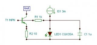
I was experiencing CCSs about 25 years ago, the currents in the biasing LEDs and the CCS output were both about 3 mA. I just observed the results on a little scope and can't say what were the oscillation frequencies encountered.
However, Morgan and Roender who are certainly more skilled than me arrived at schemes similar to mine.
Here some links to a discussion about CCS in 2006 :
Roender's circuit
http://www.diyaudio.com/forums/solid-state/86626-searching-best-ccs-4.html#post1639176
As we know, bootstrapping the resistor biasing the LEDs to the negative power supply rail à la Self or à la Jung much enhances PSRR.
Darkfenriz used a Zener diode
http://www.diyaudio.com/forums/solid-state/86626-searching-best-ccs-3.html#post1034331
My comments
http://www.diyaudio.com/forums/solid-state/86626-searching-best-ccs-3.html#post1034475
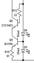
In Roender's circuit, replacing R12 by a short and D6 with a 1 kOhm resistor (about 1.6 mA bias current) gave almost the same performance. I was pleased to discover that Morgan Jones used the same circuit in his valve amps.
Regards.
Hi Bob,
I was experiencing CCSs about 25 years ago, the currents in the biasing LEDs and the CCS output were both about 3 mA. I just observed the results on a little scope and can't say what were the oscillation frequencies encountered.
However, Morgan and Roender who are certainly more skilled than me arrived at schemes similar to mine.
Here some links to a discussion about CCS in 2006 :
Roender's circuit
http://www.diyaudio.com/forums/solid-state/86626-searching-best-ccs-4.html#post1639176
As we know, bootstrapping the resistor biasing the LEDs to the negative power supply rail à la Self or à la Jung much enhances PSRR.
Darkfenriz used a Zener diode
http://www.diyaudio.com/forums/solid-state/86626-searching-best-ccs-3.html#post1034331
My comments
http://www.diyaudio.com/forums/solid-state/86626-searching-best-ccs-3.html#post1034475
In Roender's circuit, replacing R12 by a short and D6 with a 1 kOhm resistor (about 1.6 mA bias current) gave almost the same performance. I was pleased to discover that Morgan Jones used the same circuit in his valve amps.
Regards.
Hi forr,
Thanks for this info. Good stuff. I cover current sources in my book in figures 2.10a-f, but those current sources are not as sohpisticated.
Do you know if anyone has simulated the current source you had oscillation issues with, and whether the simulation pointed to instability?
Cheers,
Bob
Howdy,
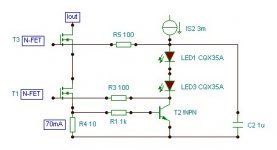
Without a base stopper the LED CCS is not stable either.
Data?
Hi forr,
Thanks for this info. Good stuff. I cover current sources in my book in figures 2.10a-f, but those current sources are not as sohpisticated.
Do you know if anyone has simulated the current source you had oscillation issues with, and whether the simulation pointed to instability?
Cheers,
Bob
Hi Bob,
There is some goof stuff in this thread :
http://www.diyaudio.com/forums/solid-state/173005-improved-current-source-sink.html
My ancient experiences probably suffered from lack of local decoupling and inadequate breadboard implementation. Instabilities and unexepcted oscillations may be due to a reactive input impedance on the base or gate of a transistor. This is usually cured by base stoppers.
Erik Margan wrote a paper on the subject in Electronics World, April 1998, page 311-312. I'll scan it and send it to interested persons (leave me an MP).
I recently made up my mind that CCSs more sophisticated than the ones you present in your book (if your R2 is bootstrapped to the negative rail power supply rail) are generally unnecessary.
Regards.
Perhaps I wasn't clear for which my apologies. I was asking for data supporting your declaration that an LED-based CCS is not stable without a base stopper. I've built a few dozen CCS with that topology and never saw an oscillation. So if you have contrary data, I'd like to see it.
The capacitor in your diagram is curious, given the low dynamic impedance of LEDs.
The capacitor in your diagram is curious, given the low dynamic impedance of LEDs.
Hi SY,
instability is a function of Iout, you may get away with no base stopper at low Iout levels, but knowing the mechanism, I always use a base stopper.
In a wider perspective, I never apply a capacitor directly to the base.
Hi WuYit,
Can you explain that mechanism, as you see it? Have you seen this in simulation? I have not experienced oscillations in ordinary current sources without base stoppers.
Cheers,
Bob
SY,
I did clearly understand you, but having problem with providing data. A low source impedance is just one cause of instability, it´s also a matter of topology, device type, gain, feedback, bandwidth and so on. I once "forgot" about the base stopper heavy oscillation as a result and became quickly convinced of the need for it and I`m not the only one. Base / gate stoppers can sometimes be omitted in various places, the question is whether doing so is an advantage or not.
LEDs are noisy, the capacitor is optional.
http://www.diyaudio.com/forums/parts/35821-some-noise-measurements-leds-zener-diodes.html
The do get noisier as they age , some OEM's determine MTBF as 1/f noise increases with age. For CCS use , I just bypass with 1000pF cap - all is good.
I won't use one for an IPS CCS , but my hawksford cascode has 2 greens and my OPS has 2 red's - in those applications , I still get a silent circuit.
Ha ! - PS , under a bright CFL - the external light will affect (modulate) the led exposed to it. (keep your CCS dark )
)
OS
The do get noisier as they age , some OEM's determine MTBF as 1/f noise increases with age. For CCS use , I just bypass with 1000pF cap - all is good.
I won't use one for an IPS CCS , but my hawksford cascode has 2 greens and my OPS has 2 red's - in those applications , I still get a silent circuit.
Ha ! - PS , under a bright CFL - the external light will affect (modulate) the led exposed to it. (keep your CCS dark
)OS
Last edited:
intrinsically produced distortion in Class-D amps
Hi Bob,
More on this subject can be found here: http://dr.ntu.edu.sg/bitstream/hand... Analog PWM Class D Amplifiers.pdf?sequence=1
(THD of closed-loop analog PWM class-D amplifiers)
Cheers,
E.
[snip]
By Ray de Velder
[snip]
His understanding of more complex amplifier systems seems lacking in some areas, e.g. higher order poles, and class-D amplifiers. For example, he does not mention (maybe because he does not know) that conventional class-D amplifiers (with -ve feedback) or the self-oscillating systems he mentions, intrinsically produce distortion, even if the electronics is assumed perfect.
[snip]
_____
I'm a bit puzzled by the class D comments, but that is a big subject whose surface I have only scratched. Maybe I missed something there. If one of you guys can articulate in more detail what he may be referring to that would be helpful. Or maybe one of the guys on the class D forum can set me straight. There's always the second edition to think about.
Cheers,
Bob
Hi Bob,
More on this subject can be found here: http://dr.ntu.edu.sg/bitstream/hand... Analog PWM Class D Amplifiers.pdf?sequence=1
(THD of closed-loop analog PWM class-D amplifiers)
Cheers,
E.
Hello!
Sorry that I write here because is a popular thread and many people read.
I'm looking for specific website URL that is contain an interesting negative feedback. I didn't put in my favorites and not find with google.
The main thing that I right remember, that the site has firstly conventional power amp with global feedback generally the feedback come from last stage so it's center of output transistor pair in complementer topology.
On the site lately author used minimum two output transistor pair and the feedback connect only to one of them and the other pair not connect to first and that is the last stage.
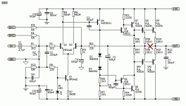
May be the schematic helps.
So I'm looking for this unusual feedback site.
Thank you
Gyuri
Sorry that I write here because is a popular thread and many people read.
I'm looking for specific website URL that is contain an interesting negative feedback. I didn't put in my favorites and not find with google.
The main thing that I right remember, that the site has firstly conventional power amp with global feedback generally the feedback come from last stage so it's center of output transistor pair in complementer topology.
On the site lately author used minimum two output transistor pair and the feedback connect only to one of them and the other pair not connect to first and that is the last stage.
May be the schematic helps.
So I'm looking for this unusual feedback site.
Thank you
Gyuri
Attachments
Hi topicreader,
I think you mean :
The ALTMANN SPLIF Amplifier Topology
From my point of view, there is a complete lack of understanding of the global NFB's benefits by the author.
I think you mean :
The ALTMANN SPLIF Amplifier Topology
From my point of view, there is a complete lack of understanding of the global NFB's benefits by the author.

Hi topicreader,
I think you mean :
The ALTMANN SPLIF Amplifier Topology
From my point of view, there is a complete lack of understanding of the global NFB's benefits by the author.
Woow!
You are a God, thank you very much.
Bye
Gyuri
- Home
- Amplifiers
- Solid State
- Bob Cordell's Power amplifier book