anybody want to create a pcb layout for this schematic pls...
<a href="http://s1136.photobucket.com/albums/n481/viewsonic3/?action=view¤t=quasibjt.jpg" target="_blank"><img src="http://i1136.photobucket.com/albums/n481/viewsonic3/quasibjt.jpg" border="0" alt="Photobucket"></a>
<a href="http://s1136.photobucket.com/albums/n481/viewsonic3/?action=view¤t=quasibjt.jpg" target="_blank"><img src="http://i1136.photobucket.com/albums/n481/viewsonic3/quasibjt.jpg" border="0" alt="Photobucket"></a>
The link that you are posting is not working (at least for me) The forum should be creating a clickable link embeded in your post. Not sure why its not working, but I would have checked it out if it had woked. Try again.")
sorry about that, pls copy and paste this
http://i1136.photobucket.com/albums/n481/viewsonic3/quasibjt.jpg
hi peranders, yes i didnt have a wide knowledge on this profession,
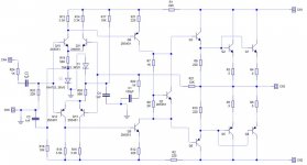
this schematic was tried and tested on +75 0 -75 volts with 3 pairs of output and it works well.
but i dont have a pcb layout for it and im not good on making it.
heres much better schematic http://s1136.photobucket.com/albums/n481/viewsonic3/?action=view¤t=quasibjt2.gif
thanks
this schematic was tried and tested on +75 0 -75 volts with 3 pairs of output and it works well.
but i dont have a pcb layout for it and im not good on making it.
heres much better schematic http://s1136.photobucket.com/albums/n481/viewsonic3/?action=view¤t=quasibjt2.gif
thanks
Last edited:
yes
yes thats the design, could you make a pcb layout?
Q3=mje15032
Q6=mje15033
Outputs=c5200
thanks
Is this the design that you want a PCB for?
yes thats the design, could you make a pcb layout?
Q3=mje15032
Q6=mje15033
Outputs=c5200
thanks
Last edited:
because it is working and tested, havent hear the sound yet but this is a working circuit.
it came from a local audio site.
here it is: http://www.electronicslab.ph/forum/index.php?topic=26603.0
it came from a local audio site.
here it is: http://www.electronicslab.ph/forum/index.php?topic=26603.0
Last edited:
Hi Carlsburg
I tend to agree with Bill, this is a DIY site where you will find loads of help, but NOT people willing to help those who don't or won't try.
I am still learning every day as this is not my profession either, the fun is in trying or trying to find out the answers, not to join and ask others to do the work for you
Try this site, I found it really easy to learn the software and now use it to design my own parts and PCB's every week.
DipTrace - Professional Schematic & PCB Design Software
Cheers and good luck
Hi Carlsburg
Go to the download page and hit,
DipTrace 2.1 Freeware
All programs and all libraries. 300 pins limit, non-profit use only.
This is what I use, I don't think you will hit the 300 pin limit for a while.
Glad to help, shot me a message if you get stuck.
Go to the download page and hit,
DipTrace 2.1 Freeware
All programs and all libraries. 300 pins limit, non-profit use only.
This is what I use, I don't think you will hit the 300 pin limit for a while.
Glad to help, shot me a message if you get stuck.
Hi Carlsburg
I tend to agree with Bill, this is a DIY site where you will find loads of help, but NOT people willing to help those who don't or won't try.
There are numerous free pcb packages on the internet.
There are also paid for packages which usually have better functionality than the free ones but do tend to be harder to use.
A pcb package with plenty of error checking is best as one fault and the pcb needs hacking to get it going.
Keep your pcb as tight as possible with thick tracks for power and you shouldnt go too far wrong.
i understand you what you are saying, ok ill try to build it with the site you gave.
do i have to register first or download it without registering?
thanks
Why do you need software? For decades people used pencil and paper. For one very simple board an easy way to make a one-off PCB is to first drill the holes, make sure the components fit. then connect the holes with 1/4 or 1/8 inch wide black vinyl tape. Stick it down good then etch the board.
You really can't do complex digital projects this way but audio amps tend not to use those tiny parts. You can sketch the PCB layout right on the copper board with pencil then when you like cover the pencil lines with tape.
I'd split a complex project up and use several of these PCBs. One for the power supply, one for left and right power section and so one. Easier to debug.
If you are new to PCB designing then build a working power supply first. Use the vinyl tape method. maybe make a few of those, then a simple power section for an amp. Only then try something complex and maybe get into software.
One other construction technique, that was used in the electronics industry before PCBs were invented is "turret boards". These are associated to vacuum tubes but only because that was the technology of the day. Turrets can support a SS design. This can be built with simple hand tools. They are easy to design too because the layout can closely resemble the schematic. It was the best available technology in the 1940's
See this for more info.
http://en.wikipedia.org/wiki/Turret_board
Last edited:
Why do you need software?
You dont for simple layouts.
Once there is more than say a dozen components then errors can creep in and cause all sorts of problems.
There are plenty of free cad packages around now which will allow the iron on method before developing.
A major advantage of pcb cad software is the error checking between sch and pcb and also for clearances etc.
- Status
- This old topic is closed. If you want to reopen this topic, contact a moderator using the "Report Post" button.
- Home
- Design & Build
- Software Tools
- pcb layout for-