I vote for aluminum for the Standel lower chassis - the BUD AC401 (which is the exact dimensions of the 25L15 original) is plenty sturdy enough if the amp isn't dropped, and Al is a much better electrical conductor than steel, which is still far better than titanium - which positively sucks in that regard. (If you use titanium, be prepared to spend big bucks - not only for the material, but for the tools you'll need to work it - and to run a bunch of ground busses since it conducts only about half as well as tungsten!)
Bud
Bud
Ultra Linear Operation Explained
Danny Hall - Please disregard my last post asking about UL. I have just reviewed a few sites and I now have a 200% clearer idea of what this is.
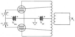
The centretap on most transformers serves as Ground, as is the case in the 196x Rickenbacker M-30 and the 195x Standel 25L15.
BUT this does not necesarily mean that the transformer has UL taps (leads coming out of the tranny) at the 43% mark - the very thing you need to create UL, as each of these two(2) leads (at 43% in the tranny) each go to the screens of each tube.
Here's a good site for others seeking clarification:
Ultralinear Guitar Amplifiers
Thank you,
Frank
Danny Hall - Please disregard my last post asking about UL. I have just reviewed a few sites and I now have a 200% clearer idea of what this is.
The centretap on most transformers serves as Ground, as is the case in the 196x Rickenbacker M-30 and the 195x Standel 25L15.
BUT this does not necesarily mean that the transformer has UL taps (leads coming out of the tranny) at the 43% mark - the very thing you need to create UL, as each of these two(2) leads (at 43% in the tranny) each go to the screens of each tube.
Here's a good site for others seeking clarification:
Ultralinear Guitar Amplifiers
Thank you,
Frank
Attachments
I'd guess not magnetically, since it's non-ferrous... and probably not much Faraday shielding either, with it's low conductivity. For the best shielding, use a copper-clad steel chassis. (But I've found proper spacing and orientation of the power and output transformers on an aluminum chassis works just as well.)
Not that it's any of my business, but I think when you're cooking up a Standel-inspired amp, and just guessing at the circuit, "clone" isn't the right word. "Clone", to me would mean that you've got the authentic schematic in front of you and you're going to build something that is as close as you can get to the real thing.
</hijack>
- Scott
</hijack>
- Scott
Clones, replicas, copies, fakes, etc
In my opinion,
I think it is kool to call custom made amps 'clones' or close copies, as opposed to having to type out "an amp derived from' or 'based on' or 'highly influences by'. I agree that they are not exact duplicates, which is really what these terms mean. If the circuit matches quite close, and the sound is quite close, and the speaker type is close, to save breathing air(and sanity) let's call it that.
To call an amp a Replica of another, however, is a totally different story. This would have to be pretty d*mn close to the real thing. I'm thinking Lorenz Stark from Germany, and his Ray Butts echosonic Replica.
My 2cents,")
Frank
In my opinion,
I think it is kool to call custom made amps 'clones' or close copies, as opposed to having to type out "an amp derived from' or 'based on' or 'highly influences by'. I agree that they are not exact duplicates, which is really what these terms mean. If the circuit matches quite close, and the sound is quite close, and the speaker type is close, to save breathing air(and sanity) let's call it that.
To call an amp a Replica of another, however, is a totally different story. This would have to be pretty d*mn close to the real thing. I'm thinking Lorenz Stark from Germany, and his Ray Butts echosonic Replica.
My 2cents,
Frank
807 Voltages
Hey buddy,
Well, MY tranny outputs 700V total, that's 350V per side. Each TOP PIN connector on the 807s should have around say, 455V D.C..
I'm looknig at some schematics here (for the 1953 Standel 25L15), and looks like PIN #2 for the 807s is being fed around 28V A.C.
The B+ that is split to both PIN #3s via two 100Ohm/1Watt resistors should be around 460V D.C. or so.
It would be great to have the readings from others.
Hope this helps!
Frank
Can someone who has built a Standel clone post your 807 plate and screen voltages?
I'm still in the planning stage for my clone. Thanks in advance
Hey buddy,
Well, MY tranny outputs 700V total, that's 350V per side. Each TOP PIN connector on the 807s should have around say, 455V D.C..
I'm looknig at some schematics here (for the 1953 Standel 25L15), and looks like PIN #2 for the 807s is being fed around 28V A.C.
The B+ that is split to both PIN #3s via two 100Ohm/1Watt resistors should be around 460V D.C. or so.
It would be great to have the readings from others.
Hope this helps!
Frank
Frank, 460VDC signicantly exceeds the screen voltage limits on the 807. Has that caused you any concern or early tube failures? I'm thinking of adding a regulated screen supply to keep the voltage closer to its 300vdc limit.
Scott is right my build will not really be a clone, but I'm trying to build it as near as possible as I can with the snippets of schematics that have been floating around.
Jonathan
Scott is right my build will not really be a clone, but I'm trying to build it as near as possible as I can with the snippets of schematics that have been floating around.
Jonathan
Frank may have meant 260v, not 460 (typo/fat-finger?)... 460 wouldn't have even been electrically possible using the 700vct transformer and the power supply circuitry of the original. (The screen voltage is taken off the B+ through a 20k ww resistor to one of the 20uF 4-section filter cap sections.)
With a Hammond 273BX and 5U4 rectifier, I'm measuring 425v at the 807 plates and 240v on the screens with only one alteration of the original schematic - the addition of a 36k 2w bleeder to ground on the screen line, just upstream from the 100-ohm screen resistors. That's a change I had to make earlier when I used a 750v transformer from an old Williamson amp and found the screen V too high, and had to modify the circuit to drop it. I liked the result, as it provides some extra regulation for the screens, but it works fine without the bleeder, too.
With a Hammond 273BX and 5U4 rectifier, I'm measuring 425v at the 807 plates and 240v on the screens with only one alteration of the original schematic - the addition of a 36k 2w bleeder to ground on the screen line, just upstream from the 100-ohm screen resistors. That's a change I had to make earlier when I used a 750v transformer from an old Williamson amp and found the screen V too high, and had to modify the circuit to drop it. I liked the result, as it provides some extra regulation for the screens, but it works fine without the bleeder, too.
Ot pt choke - transformers / heavy iron
Hi Jonathan!
Last winter I found the sweetest power transformer: New In Box never used 1950's Hammond 273BX. Came with the original manual, 30$ from the guy!!! It's got the old matt black Crinkle finish on it, and the metal badge logo on the front. It's B+ tap is 350V per side (push-pull) and centertapped, and I can get around 175ma maximum current draw. The new ones that Hammond makes get around 201ma. max.
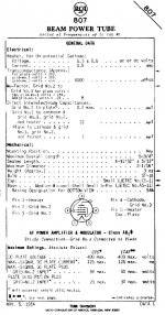
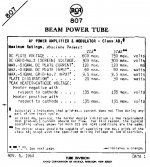
For the Output transformer, I like the Hammond 1650PP. It is a special 10lbs Potted Transformer, Primary Impedance 6,600 c.t., 60 Watts power rating, 200ma MAX DC per side, 4-8-16 Ohms speakers, and is listed as useful for 807/6L6/5881/KT88/EL34/6146B/6550B tubes. Since the output transformer's inputs are fed from the 807's plates, I looked up the 807 tube specs from RCA. Their spec sheet for the 807 tube (http://sarris.info/main/files/807rca.pdf) indicates that the MAX DC Current for the plate is around 125ma., so I think that if this OT handles up to 200ma, we're okay.
It would be interesting to know what other users have selected for their build(s). Edcor do make some very nice options.
Here's also some ideas for the chokes needed for the 25L15. It would be great to hear what others have chosen for their build(s):
Needed: 200ma 1.5H 90 ohms and 70ma 15H 90 ohms
------
Stancor: 200ma 1.5H 85ohms - model C-2327 and 75ma 15H 400ohms - model C-1002
Hammond: 200ma 1.5H 56ohms 400V - model 156R and 75ma 15H 411ohms 400v - model 1
Cheers!
Frank
Frank, I'm curious what iron did you use? I'm thinking of using a power transformer I have thats a rewind repaired cannibalized from a Fender Pro Reverb. Edcor 6.6k 40watt OP transformer.
Jonathan
Hi Jonathan!
Last winter I found the sweetest power transformer: New In Box never used 1950's Hammond 273BX. Came with the original manual, 30$ from the guy!!! It's got the old matt black Crinkle finish on it, and the metal badge logo on the front. It's B+ tap is 350V per side (push-pull) and centertapped, and I can get around 175ma maximum current draw. The new ones that Hammond makes get around 201ma. max.
For the Output transformer, I like the Hammond 1650PP. It is a special 10lbs Potted Transformer, Primary Impedance 6,600 c.t., 60 Watts power rating, 200ma MAX DC per side, 4-8-16 Ohms speakers, and is listed as useful for 807/6L6/5881/KT88/EL34/6146B/6550B tubes. Since the output transformer's inputs are fed from the 807's plates, I looked up the 807 tube specs from RCA. Their spec sheet for the 807 tube (http://sarris.info/main/files/807rca.pdf) indicates that the MAX DC Current for the plate is around 125ma., so I think that if this OT handles up to 200ma, we're okay.
It would be interesting to know what other users have selected for their build(s). Edcor do make some very nice options.
Here's also some ideas for the chokes needed for the 25L15. It would be great to hear what others have chosen for their build(s):
Needed: 200ma 1.5H 90 ohms and 70ma 15H 90 ohms
------
Stancor: 200ma 1.5H 85ohms - model C-2327 and 75ma 15H 400ohms - model C-1002
Hammond: 200ma 1.5H 56ohms 400V - model 156R and 75ma 15H 411ohms 400v - model 1
Cheers!
Frank
Attachments
Last edited:
Screen (Grid #2 - PIN #3) Voltage
Hi again Jonathan!
Yes, 460V is way too much. But if you look at the schematics, the B+ coming in to the screens (Grid #2 - PIN #3), has a resistor going to each screen. There are always a set of identical valued 1 Watt resistors here. I have a few schematics, some indicate a pair of 100 Ohms, others show 470 Ohms (any ideas on what was used originally?). Either way, doesnt the voltage divide itself? that is to say, 230V X 2 = 460V. As you say, the RCA Data Sheet indicates that the Grid #2 (screens) can handle up to 300V, and the plates can handle up to 750V!! See the photo on this posting for the Data Sheet.
Apologies for any confusion this may have caused, and I always more than welcome any corrections to anything that I may post in error.
Thank you,
Frank
Frank, 460VDC signicantly exceeds the screen voltage limits on the 807. Has that caused you any concern or early tube failures? I'm thinking of adding a regulated screen supply to keep the voltage closer to its 300vdc limit.
Scott is right my build will not really be a clone, but I'm trying to build it as near as possible as I can with the snippets of schematics that have been floating around.
Jonathan
Hi again Jonathan!
Yes, 460V is way too much. But if you look at the schematics, the B+ coming in to the screens (Grid #2 - PIN #3), has a resistor going to each screen. There are always a set of identical valued 1 Watt resistors here. I have a few schematics, some indicate a pair of 100 Ohms, others show 470 Ohms (any ideas on what was used originally?). Either way, doesnt the voltage divide itself? that is to say, 230V X 2 = 460V. As you say, the RCA Data Sheet indicates that the Grid #2 (screens) can handle up to 300V, and the plates can handle up to 750V!! See the photo on this posting for the Data Sheet.
Apologies for any confusion this may have caused, and I always more than welcome any corrections to anything that I may post in error.
Thank you,
Frank
Attachments
Last edited:
Bobo crooks standel 25l15 schematic
Hi Ben,
Not a problem! I thought that most people already had the full schematic from one of my many other postings.
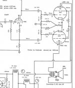
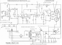
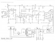
Posted here now is the rare 1953 version of the schematic.
Also, find 2 versions (0.3 & 0.8) of the same schematic cleaned up by a friend.
Cheers!
Frank
Hi Ben,
Not a problem! I thought that most people already had the full schematic from one of my many other postings.
Posted here now is the rare 1953 version of the schematic.
Also, find 2 versions (0.3 & 0.8) of the same schematic cleaned up by a friend.
Cheers!
Frank
Hi Frank,
That is a beautifully clear image of the Bob Crooks schematic you just gave us a cutout of. Be a sport and post the whole image would you please,
Thanks Ben.
Attachments
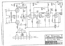
Ben, be cautious with these schematics - the "original" has a few errors, and the "cleaned-up" versions have many. Case in point: the balance pot in the 807 input circuit has nothing to do with the preamp filaments; it is there to balance the idle current on imperfectly-matched 807's. Many of the parts values are way out of line - the 100k's on either end of the 100-ohm balance pot were (and should be) 100 ohms; I doubt if it'd even work with 100k's... The cathode bias resistor (nominally 68 ohm 3w) may need to be slightly higher or lower, but probably not as high as the 180-200 ohms suggested in the "new" drawing. On the original drawing, the 6-pin Jones plug is wired incorrectly (the way it's shown, both ends of the preamp filaments would be at ground - they're really connected to pins 5-6. Pins 3 & 4 are for B+ and ground. The pinout of the 807s is wrong. I could go on...
But if you know what you're doing, you'll recognize a lot of these "mistakes". The problem is that when you find an obvious error on a schematic, you can't always be sure of the correct wiring. I've never been able to determine if those alleged "original Bob Crooks" schematics (I found copies about 6 years ago and realized I couldn't build an amp from them as drawn) are simply fakes or whether Bob inserted the errors purposely to prevent others from stealing his design. Based on what I've read, and how he started encapsulating portions of his later solid-state amps in color-coded "modules" to further disguise his schematics, I suspect it's the latter.
The only schematic of a 25L15 that I trust is one "reverse-engineered" from one of the original amps, and from which an amp that cannot be distinguished from the original has been built.
Bud
Hi. New member here. Sorry to butt in but... this is a great post! Thank you for sharing all the info. This is a very cool site, indeed, and the Standel amp is something that I find very interesting.
Oh, someone said way back that Wes Montgomery used a Standel? I think this is incorrect. In fact, his favorite recording amp was a Fender Tweed Deluxe with an alnico Jensen according to Wolfe Marshall. I have to go with that because his tone was FAT, not what I would call Standel tone at all.
Anyway, great site and great post!
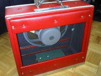
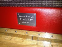
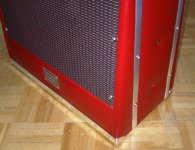
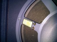
My Cabinet Is Complete
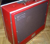
Make sure you're sitting down.... this is one of the nicest amps I've ever seen in my life. I commissioned a good friend of mine (t h a n k y o u m y f r i e n d !!) for the cab & metalwork, and the results are spectacular. I installed my 1954 JBL D-130 speaker the night the cab arrived. Now for the electronics!
Make sure you're sitting down.... this is one of the nicest amps I've ever seen in my life. I commissioned a good friend of mine (t h a n k y o u m y f r i e n d !!) for the cab & metalwork, and the results are spectacular. I installed my 1954 JBL D-130 speaker the night the cab arrived. Now for the electronics!
Attachments
- Home
- Live Sound
- Instruments and Amps
- I Have Finished My Standel 25L15 Clone