There are two problems with adding high amounts of feedback to a valve circuit, which SS doesn't suffer from:
1. The OPT has a resonance somewhere above the audio band. This means 180 degrees of phase shift, not the 90 degrees of an integrator or dominant pole typical of SS.
2. Coupling capacitors add LF phase shift, typically several lots, whereas SS is usually DC coupled.
On the other hand, the valve circuit is likely to have much better open-loop behaviour (e.g. less distortion, wider bandwidth) than a typical SS amp so it needs less feedback.
Last edited:
So adequate local feedback before the OT to fix the tube distortion, and just enough NFdbk after the OT to control the output Z. Seems the way to go. Along with very stiff power supplies and smart grounding. The missing ingredient yet is how to get minimal crossover distortion in class AB.
The missing ingredient yet is how to get minimal crossover distortion in class AB.
+ Proper idle current of better than 6L6 - clone tubes. That's it.
http://wavebourn.com/forum/download.php?id=509&f=7
The missing ingredient yet is how to get minimal crossover distortion in class AB.
Steve Bench discussed this in the "loadlines" section of the technical reports.
See: Part IV
Part V
The best way to minimize X-over is to stay as far away from Class B conditions as you can manage, consistent with dissip ratings.
So adequate local feedback before the OT to fix the tube distortion, and just enough NFdbk after the OT to control the output Z. Seems the way to go.
You don't need any GNFB if you use (lots of) feedback before the OPT, as it also lowers the Z driving the primary, which also lowers the Z at the output.
Know to me as the Loesch method, works very well IME
")
http://www.diyaudio.com/forums/tube...ective-global-fb-decent-damping-factor-2.html
It's also nice and stable.
Two ways to reduce Class B crossover distortion:
1. Use Class A instead.
2. Use proper bias - as you shift the quiescent current from true Class B to true Class A the distortion doesn't simply reduce monotonically but changes in a signal-level dependent way. Having established the right bias, maintain it by not using a standard CCS!
Common-mode feedback may help. I think Mullard (or GEC?) mentioned this in one of their books.
Those links to Steve Bench's loadlines are quite nice. That is the traditional way of minimizing crossover distortion by optimum biasing.
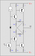
On the common mode feedback for reduction of crossover distortion, TubeCad has a SS circuit that can be modified for vacuumstate CM FdBk. (2nd diagram up from page bottom: and see attached diagram copy )
European Triode Festival and Crossover Notch Distortion and New OTL Design
The 0.1 Ohm resistors sense the currents, which can be moved into the cathodes of a P-P tube output, and the 100 Ohm resistors would provide neg. feedbacks to a differential driver stage. (resistor values get increased obviously for tube use, and only one feedback resistor from each current sense R back to the differential driver)
The current sense resistors can also go into the plate side, and Schade like feedbacks will automatically make use of the extra info. An equal resistance OT is essential then, and sending the Schade feedbacks back to the driver grids or cathodes instead is better, for more loop gain.
Hawksford has a journal paper on common mode current correction too.
A couple of interesting schemes for reduction of crossover distortion exist in the SS realm. One is to use a voltage limited class A output stage with floating power, and a class AB stage to move it's rail voltages around. (patent 4115739) Not very useful for tubes though.
Another approach is to use a current limited class A output stage with paralled class AB current boosters. This should be easy to do in tubes. Just use two sets of output tubes, one set of small triodes or Schaded Pentodes in class A bias (set for low max current, essentially similar to class AB bias here since they don't get loaded down enough to ever turn off), and the other as large Pentodes in class AB bias for large current out. The big pentodes get configured to supply most of the output current, but with high Zout. They could either be driven open loop off the same driver, or better, from current sensing feedbacks (but class AB biased) from the small tubes.
Finally, one can go all the way and just put Mosfet current boosters (high Zout) on the secondary OT side instead, then the OT can be small too.
Attachments
Last edited:
Another approach is to use a current limited class A output stage with paralled class AB current boosters. This should be easy to do in tubes. Just use two sets of output tubes, one set of small triodes or Schaded Pentodes in class A bias (set for low max current, essentially similar to class AB bias here since they don't get loaded down enough to ever turn off), and the other as large Pentodes in class AB bias for large current out. The big pentodes get configured to supply most of the output current, but with high Zout. They could either be driven open loop off the same driver, or better, from current sensing feedbacks (but class AB biased) from the small tubes.
In transistor amps it is easy, since class AB, or class B, or class C stage is configured as a follower with gain close to 1, and connected input-output across the resistor that supplies current from class A amp to the load. Smoothness of transition from class A driver output to assistance of more powerful follower is maintained by fast negative feedback.
With tubes it is problematic: it creates more of questions than gives answers: 1) how to stabilize and match amplification factors, and 2) how to get fast negative feedback if transformer is needed.
"1) how to stabilize and match amplification factors, and
2) how to get fast negative feedback if transformer is needed."
For the case where both the small and big tubes are run from the same driver or scaled drive versions, matching would be critical and would need some pots to tweek the drive levels and biasing. The small (class A) tubes would be biased up enough to handle the crossover region current requirements essentially, and since they have low output Z they can overpower the high Zout pentodes there if the big guys are not too far out of alignment (being in class AB they won't have much current capability in the crossover region anyway). At higher power the pentodes just plain take over (Schade feedbacks to the driver running the show in either case).
For the version that uses current sampled feedbacks from the small tubes to control the big pentodes, less so (for critical matching/tracking). This is similar to that "Octode" thread a while back (TubeCad had some article on it too). The signal from the class A sampled currents would control the big tubes in such a way as to minimize (nearly zero out) any AC current draw from the small tubes (local NFdbk loops with gain). So the small (class A) tubes see a very light load, but can exert total influence on the voltage output, due to their low Zout and total control of the booster pentodes (which are high Zout, before driver fdbk lowers everthing). The class A tubes only need biasing up enough to handle the very reduced loading and crossover region.
The same OT gets used for both tube sets in either design (Zpri setup for the big pentodes), since the small tubes are greatly unloaded. So local feedback from the primary assures accurate, fast control of everything via a Schade type (to driver) setup.
Trying to control some Mosfet current boosters on the secondary could have HF phase issues with the OT in between. Maybe just roll the boost off with HF.
----------------------
Re DF96:
"Having established the right bias, maintain it by not using a standard CCS!"
Are you suggesting some kind of modulated CCS? A tracking bias? Or just a very stable gyrator type bias?
Last edited:
I don't know why to transfer SS problems back to tube problems: SS amps in AB were blindly copied from tube AB amps that worked nice, and "current dumping" schemes were inventing in order to overcome SS specific problems. Tube amps did not have them (unless wrong tubes were used), so I don't see the reason to bring solution of SS - related problems to tube world where they create new problems solving nothing.
I suggest just to use right tubes for right applications. Some tubes need lower idle current to work in class AB output stage, some tubes need higher idle current, some need such current that would destroy them.
I suggest just to use right tubes for right applications. Some tubes need lower idle current to work in class AB output stage, some tubes need higher idle current, some need such current that would destroy them.
Could still be interesting to have an amp that sounds like one tube type at low level and another tube type at high level.
I remember some patents discussed here about such approach last year. But my humble experiments suggest that it is not needed at all. May be, if somebody badly wants to use 6L6 clones as if other tubes don't exist it may be a good approach, though.... But designing mi first (and last) amp with 6L6 tubes I found that since optimum don't exist the best way is to find a compromise between number of tubes and amont of distortions they produce, so 4x6L6 were used for 40W RMS output, in plain straight parallel connection with 400V B+ and 200V G2.
Last edited:
- Status
- This old topic is closed. If you want to reopen this topic, contact a moderator using the "Report Post" button.
- Home
- Amplifiers
- Tubes / Valves
- NFB question