Ahhh, ça c'est du bon travail.
(does not count, Masochist is when you show us a piccy of your hand with a straight line of holes)
Then I should drill F5 on my hand. Makes more sense.
D.
Nikon,
Consider yourself lucky....the amp could have been termed "FFF55552223333",
rather than "F5". (You would have needed a LOT more drill bits!)
Nice job..... helps to have a great center punch.... (Old trick, if you didn't use it--a piece of graph paper, to lay out the drilling grid.....)
Consider yourself lucky....the amp could have been termed "FFF55552223333",
rather than "F5". (You would have needed a LOT more drill bits!)
Nice job..... helps to have a great center punch.... (Old trick, if you didn't use it--a piece of graph paper, to lay out the drilling grid.....)
Then I should drill F5 on my hand. Makes more sense.
D.
You will no worryes bout thatStill beter that than my usual drilling last hole in wrong place

With a "center drill" set with a depth stop, one might not need either a center punch to start nor a countersink bit to finish. Anyone drilling metal should have one (in a couple of sizes).
File:CenterDrills123456.jpg - Wikipedia, the free encyclopedia
File:CenterDrills123456.jpg - Wikipedia, the free encyclopedia
I did a first hole 2mm, then enlarged it to 5mm and finally finished on both side with the tool to make the V shape holes. (These are the tools I had) I had to refine few holes with a little file.
I use a plastic printable sticker as a frame. I print what I want to drill, and stick it on the surface.
Andersonix, how are you supposed to use that bit ? Just as a normal bit ?
I should start to do the rest, but I am lazy :-(
Thanks,
Davide
I use a plastic printable sticker as a frame. I print what I want to drill, and stick it on the surface.
Andersonix, how are you supposed to use that bit ? Just as a normal bit ?
I should start to do the rest, but I am lazy :-(
Thanks,
Davide
I use a plastic printable sticker as a frame. I print what I want to drill, and stick it on the surface.
Davide
Printable sticker......great idea. Still requires and "eagle eye" and a steady hand, though. Nice job......!
maybe my center drill is worn out, but it aint any good with hand tools
for countersink, are you sure it has the right angle
well, I dont think it has
Any drilling works better with a stand or press.
It's true that the center drill has a 60 degree angle, so not perfect 90, but if the countersink is kept small enough (depending on your eyesight), it will still look OK.
For least effort, I would pick a hole size that is in a size available as a center drill (and pick a sheet thickness that is not too thick for that size center drill) and set the depth stop so it makes a nice 60 degree countersink (say under 0.020inch) in one shot.Andersonix, how are you supposed to use that bit ? Just as a normal bit ?
I should start to do the rest, but I am lazy :-(
Thanks,
Davide
The main difference from a regular drill bit is that it can't drill as deep, but it can drill as deep as its flutes.
Last edited:
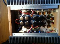
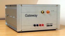
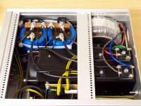
My F5 Summertime Edition (I had to add ventilation slots). Still wondering if I should have written F5 the other way around. In the process I also changed the output devices. I prefer the Toshiba, beside the fact that they have much less measurable distortion.
Best Regards,
Davide
Edit: Don't know why the site display the picture upside down.
Best Regards,
Davide
Edit: Don't know why the site display the picture upside down.
Attachments
Last edited:
My F5 Summertime Edition (I had to add ventilation slots). Still wondering if I should have written F5 the other way around. In the process I also changed the output devices. I prefer the Toshiba, beside the fact that they have much less measurable distortion.
Best Regards,
Davide
Edit: Don't know why the site display the picture upside down.
Which Toshiba devices are you using?
I am using 2SK1530/2SJ201. The first try was a textbook F5, with IRF. The actual one has no termistors and no current limiting. I may add the current limiting when the terror todler comes back home after summer. He likes to play with the speakers cables, and already once he shorted the output. The fuse blowed before the MOSFET.
This time I trimmed the distortion down, but I think that the main benefit comes from the fact that N and P parts are complementary, although mine are not matched.
BR,
Davide
This time I trimmed the distortion down, but I think that the main benefit comes from the fact that N and P parts are complementary, although mine are not matched.
BR,
Davide
My F5 Summertime Edition (I had to add ventilation slots). Still wondering if I should have written F5 the other way around.
Davide, by "written F5 the other way around", do you mean so that it's more easily read from the other end of the amp? If so, it almost looks as though your screw holes are symmetrical--can it be as easy as unscrewing and rotating the top cover? (Although I suspect you've already considered that...!)
Great looking job, and good choice of semiconductors......
F5 alive!
I posted a quick video on youtube... with my bias readings...
YouTube - f5 amp
I've also got an initial sound demo (connected to my ipod & optimus speakers)
(ok, they're my computer desktop speakers )
http://www.youtube.com/watch?v=VW7MWNZsZUs
(this is private if you want to see this, send me an IM with your youtube id, or email address)
I posted a quick video on youtube... with my bias readings...
YouTube - f5 amp
I've also got an initial sound demo (connected to my ipod & optimus speakers)
(ok, they're my computer desktop speakers
)http://www.youtube.com/watch?v=VW7MWNZsZUs
(this is private if you want to see this, send me an IM with your youtube id, or email address)
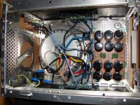
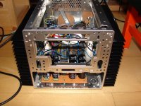
Another F5
It has been playing all day now and I should have listened to everybody here about the heatsink rotation. (it gets bloody hot). But other then that it sounds brilliant. Re-living all my favorite recordings. Now I'll take it apart again and build it properly.
Thanks Nelson!
It has been playing all day now and I should have listened to everybody here about the heatsink rotation. (it gets bloody hot). But other then that it sounds brilliant. Re-living all my favorite recordings. Now I'll take it apart again and build it properly.
Thanks Nelson!
Attachments

Zen build from scrap
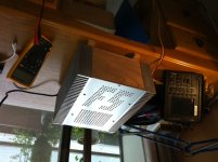
This is the first Zen I've build, simply to find out how it sounds and to make some use of salvaged parts I had lying around. It is not exactly beautiful, but made almost completely out of scrap. Along with that it is quite compact, measures only 'bout 14cm x 24cm x 29cm. I got it almost finished today, it is only missing an adequate fan controller. Well, a 'power' LED too.
I didn't test it yet, since I don't have a variac here at home. I'll do that tomorrow at work. I'm a bit afraid to simply plug it in and see what happens...
Here's some info on the parts I used:
!
The amplifier itself is built on perfboard with each power transistor mounted on one part of the heatsink, which is comprised of four equal profiles. I didn't spend the amp a volume pot, since it's going to be placed somewhere near the bottom, next to my PC. Since the computer also uses a fan, the one in the amp won't be much of a problem. At least I hope so.
Regards,
Lasse
This is the first Zen I've build, simply to find out how it sounds and to make some use of salvaged parts I had lying around. It is not exactly beautiful, but made almost completely out of scrap
. Along with that it is quite compact, measures only 'bout 14cm x 24cm x 29cm. I got it almost finished today, it is only missing an adequate fan controller. Well, a 'power' LED too. I didn't test it yet, since I don't have a variac here at home. I'll do that tomorrow at work. I'm a bit afraid to simply plug it in and see what happens...
Here's some info on the parts I used:
Toroid with 2 secondaries, 24V/6,2A each
2 huge capacitors rated 180'000uF at 35V, Nippon Chemi-Con
2 air core coils 1,5mH made of 18 gauge (1mm diam.) copper wire
another 2 caps 15'000uF/50V each
heatsink 8cm x 8cm x 20cm w/ Papst fan (got that from eBay some years ago)
nice aluminum case equipped with a huge mains filter
Simply astonishing what people throw away 2 huge capacitors rated 180'000uF at 35V, Nippon Chemi-Con
2 air core coils 1,5mH made of 18 gauge (1mm diam.) copper wire
another 2 caps 15'000uF/50V each
heatsink 8cm x 8cm x 20cm w/ Papst fan (got that from eBay some years ago)
nice aluminum case equipped with a huge mains filter
!The amplifier itself is built on perfboard with each power transistor mounted on one part of the heatsink, which is comprised of four equal profiles. I didn't spend the amp a volume pot, since it's going to be placed somewhere near the bottom, next to my PC. Since the computer also uses a fan, the one in the amp won't be much of a problem. At least I hope so
.Regards,
Lasse
Attachments
- Home
- Amplifiers
- Pass Labs
- Pictures of your diy Pass amplifier