@ Bob Cordell
Hi, admittedly i havn't been able to read all the posts, or seen the circuit diagram,so forgive me if i appear to intrude somewhat, but i felt compelled to post, if only to possibly gain some insight, as well as "hopefully" offering some.
Re -
I tend to agree, as that "might" induce more nasties than it keeps out ? A dedicated quasi smoothed common "could" be created that "might" serve that purpose ? Or just run a non screened cable, but clear of any inducements.
Wouldn't doing that negate any desired benefits, as i would have expected a driving signal to accompany a driving reference point, ie common/ground near the drive ?
Also would that not create a pole with the FB resistor ?
I'm picturing your proposed setup to look like the att.
Regards
Hi Zero,
Feel free to jump in - the water's warm
.Using a non-screened cable is probably fine. If one uses a screened cable in such a situation, grounding it at both ends might create an undesirable ground loop that could induce garbage into the center conductor.
The impedance at the output node of the amplifier is quite low, so a little bit of capacitance from a shielded feedback cable will be of no consequence.
Cheers,
Bob
FB on the FB about FB !
Might be where you are, lucky you
I agree.
Indeed, i wasn't proposing that though it's Big non no.
When i said "as i would have expected a driving signal to accompany a driving reference point, ie common/ground near the drive" i was speaking generally in response to your
As far as i'm aware, the input stage ground isn't a "driving reference point" to the FB resistor ? The driving is coming the other way from the output, isn't it ?
Your da boss
Thanks, have a nice weekend
@ Bob Cordell
Feel free to jump in - the water's warm
Might be where you are, lucky you
Using a non-screened cable is probably fine.
I agree.
If one uses a screened cable in such a situation, grounding it at both ends might create an undesirable ground loop that could induce garbage into the center conductor.
Indeed, i wasn't proposing that though
it's Big non no. When i said "as i would have expected a driving signal to accompany a driving reference point, ie common/ground near the drive" i was speaking generally in response to your
I would ground only one end of the feedback shielded cable and that would be the end near the input stage
As far as i'm aware, the input stage ground isn't a "driving reference point" to the FB resistor ? The driving is coming the other way from the output, isn't it ?
The impedance at the output node of the amplifier is quite low, so a little bit of capacitance from a shielded feedback cable will be of no consequence.
Your da boss
Thanks, have a nice weekend
As far as i'm aware, the input stage ground isn't a "driving reference point" to the FB resistor ? The driving is coming the other way from the output, isn't it ?
Input stage ground is usually isolated (lifted) from "clean earth" by 2 diodes/5-10R resistor. I ran my shield from it. I observed modulation on the CRO.This was most likely induced by crossing rails w/ heavy currents.
Either with a non-shielded return (purple wire) or the output on the shield , the "lifted ground" on the IPS was totally flatline. I don't fully remember , but Andrew T. and I decided that running the very same output signal on the shield would isolate the OP feedback return on it's way to my voltage boards 33k NFB resistor. This worked very well on several "long" (4-5 pairs) power output boards.
CONFIRMED !By B. Cordell - The impedance at the output node of the amplifier is quite low, so a little bit of capacitance from a shielded feedback cable will be of no consequence.
RAIL TRACKS - read this , Enduring Class B layout mythology
I always suspected this , in my study of the hundreds of OEM's (pro amps). Even in the luxman m-800a ($16K) or B-1000f ($30K +) - below 1-3 , you will find no twisted wires or other "voodoo" ... lots of copper , but no "myths".
PCB has layout similar to mine augmented with copper bars (below 3).
I have schema's for BOTH. Those luxman's use a refined hawksford cascode ,8 pair toshiba BJT - triple OP , hence my revival of it (LX -with cordell's "DBT") cool:
OS
Attachments
Hi,
I just read Ostripper's link about class B PCB mythodology. It looks like running the power rails close to eachother is not the full Eureka after all.
We might add that running power rails close to eachother includes a warning. Say each rail is about 75V, the potential gap between them is 150V. Running them just some mm apart from eachother is not safe as (in worst case) it could cause arcing.
It is true that in class B operation induction field cancellation (caused by the high currents) is not possible.
As this is about the induction field or current field
Is tension or voltage field of any importance? Is cancelling here of any importance? This is out of my knowledge but if anyone has the right answer it would be nice to know
cheers,
Olivier
improving psrr
Hi Samuel,
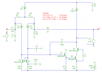
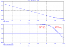
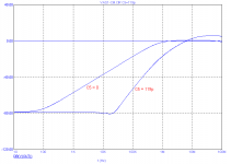
Here are some simulation figures. Indeed, the PSRR cap has some effect on the phase margin, but not that much. In the test circuit as shown below (fig.1), only two degrees (fig.2). You also worried (in a PM) about extra distortion, induced by nonlinearities of the current mirror. Well, you are right. Distortion does increase, that is, if the cap is connected as previous suggested (see C4). In this case the THD20 rises from 0.144 to 0.198 ppm.
But if we tie this cap to the emitter degen. resistor of the current mirror (see C5), than the distortion drops to 0.115 ppm.
Fig. 2: Gain and phase response of the global FB loop.
Fig. 3: PSRR of the negative rail.
(Trannies of the IPS and OPS have been replaced by ideal components to avoid swamping by distortion from other sources.)
Cheers,
E.
Cheers,
E.
I'm aware of this, but then they also affect open-loop gain. It's been years back since I've looked into this, but IIRC the effect was gross enough to make the technique unusable.
Samuel
At frequencies of interest the effect is virtual zero (at least in this application). Even at 10MHz the OLG is only 0.4dB less. Is that what you call gross enough to make the technique unusable?
Cheers,
E.
Hi Samuel,
Here are some simulation figures. Indeed, the PSRR cap has some effect on the phase margin, but not that much. In the test circuit as shown below (fig.1), only two degrees (fig.2). You also worried (in a PM) about extra distortion, induced by nonlinearities of the current mirror. Well, you are right. Distortion does increase, that is, if the cap is connected as previous suggested (see C4). In this case the THD20 rises from 0.144 to 0.198 ppm.
But if we tie this cap to the emitter degen. resistor of the current mirror (see C5), than the distortion drops to 0.115 ppm.
Fig. 2: Gain and phase response of the global FB loop.
Fig. 3: PSRR of the negative rail.
(Trannies of the IPS and OPS have been replaced by ideal components to avoid swamping by distortion from other sources.)
Cheers,
E.
Thanks Bob.Hi Edmond,
Its good to see you back!
Cheers,
Bob
Cheers,
E.
Attachments
Input stage ground is usually isolated (lifted) from "clean earth" by 2 diodes/5-10R resistor. I ran my shield from it. I observed modulation on the CRO.This was most likely induced by crossing rails w/ heavy currents.
Either with a non-shielded return (purple wire) or the output on the shield , the "lifted ground" on the IPS was totally flatline. I don't fully remember , but Andrew T. and I decided that running the very same output signal on the shield would isolate the OP feedback return on it's way to my voltage boards 33k NFB resistor. This worked very well on several "long" (4-5 pairs) power output boards.
CONFIRMED !
RAIL TRACKS - read this , Enduring Class B layout mythology
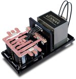
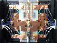
I always suspected this , in my study of the hundreds of OEM's (pro amps). Even in the luxman m-800a ($16K) or B-1000f ($30K +) - below 1-3 , you will find no twisted wires or other "voodoo" ... lots of copper , but no "myths".
PCB has layout similar to mine augmented with copper bars (below 3).
I have schema's for BOTH. Those luxman's use a refined hawksford cascode ,8 pair toshiba BJT - triple OP , hence my revival of it (LX -with cordell's "DBT") cool:
OS
Hi OS,
Thanks for bringing GK's comments to my attention - those in regard to layout and wiring for controlling the magnetic radiation of nonlinear fields from the top and bottom output stage rail currents in class B amplifiers. That is not mythology as he calls it, and I am very surprized that he does not understand the mechanism. Glenn is a pretty smart guy. Apparently he is unfamiliar with Ed Cherry's very important JAES paper on this subject:
Cherry, E. M., “A New Distortion Mechanism in Class B Amplifiers”, J. Audio Eng. Soc., vol. 29, no. 5, May 1981.
It mention the issue and reference Cherry on page 122 in my book. Perhaps in my earlier post I was not sufficiently clear in my explanation and maybe this caused Glen's confusion.
If we run a sine wave through a class AB output stage and look at the currents in each of the rails we will see a half-wave rectified sinusoid. Everyone knows that this is a very highly distorted replica of the audio signal and contains much in the way of high-order distortion and will emit high-order distortive magnetic fields from each rail wire.
However, we can recognize that the SUM of the rail currents from the top and bottom half of the output stage is a reasonably linear representation of the signal current that is flowing into the loudspeaker (apart from base current and other minor lost current, it has to be the same). If those two rail wires are twisted together, their magnetic fields will ADD, resulting in a linear magnetic field representative of the signal. This sum will have very little distortion in it. The same argument holds for having the P and N parts of the output stage in close proximity, such as by physical interleaving of the output devices, so that their created magnetic fields will tend to SUM to a more linear representation of the signal.
So far I have been using the term SUM rather than cancel. Perhaps this is what threw Glen off (but he should know better). The fundamental energy certainly does sum - no one is saying that that cancels out. However, because the sum adds to a linear quantity, it means that the individual distorted portions of the two rail signals actually did cancel out. I should have been more clear in my description.
Cheers,
Bob
SUM makes all the difference. Will just running the rails close together (not twisted) or keeping them very far apart and separate from anything else (where they would not sum or induce a field into anything else) , be the same ?
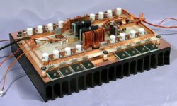
This leads to the second question ... why is this "optimization" not (widely)used by the OEM's ? Especially in the "high-end" (Genesis Stealth ... those $10K luxmans)... Even the ADCOM (below). No twisted wires there , either ??
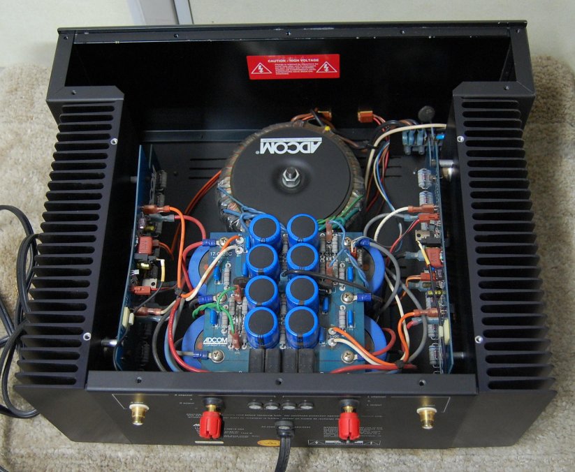
Do they feel that the gains obtained by doing so are too trivial to include in their products ? A common practice where there is NO wiring (all PCB traces) is to run the rails together along the path they take on the main amp board. The ground(s) run separately , not to be contaminated by the rail fields (or the larger "summed one"). It was these real world observations that lended credibility to GK's argument.
Personally , I'm open to any improvement.
Please comment on your triple (my post with the "DBT" question) ... thanks
OS
This leads to the second question ... why is this "optimization" not (widely)used by the OEM's ? Especially in the "high-end" (Genesis Stealth ... those $10K luxmans)... Even the ADCOM (below)
. No twisted wires there , either ??
Do they feel that the gains obtained by doing so are too trivial to include in their products ? A common practice where there is NO wiring (all PCB traces) is to run the rails together along the path they take on the main amp board. The ground(s) run separately , not to be contaminated by the rail fields (or the larger "summed one"). It was these real world observations that lended credibility to GK's argument.
Personally , I'm open to any improvement.
Please comment on your triple (my post with the "DBT" question) ... thanks
OS
If those two rail wires are twisted together, their magnetic fields will ADD, resulting in a linear magnetic field representative of the signal. This sum will have very little distortion in it. The same argument holds for having the P and N parts of the output stage in close proximity, such as by physical interleaving of the output devices, so that their created magnetic fields will tend to SUM to a more linear representation of the signal.
Bob
Hi bob,
The wires s current induced magnetic field will cancel only
if each wire carries the same current but in opposite direction.
Thus, in a class AB amp, there will be no cancellation if the wires
are twisted , unless this is a bridged amp where one amp s
rail is twisted with the other amp s opposite rail...
As for class AB, one wire s magnetic field will simply
be induced in the other wire totaly in phase,
reducing in some extent the rail to rail AC variation
since the same AC signal will be applied to the rails;
though the AC signal in respect to ground will
stay exactly the same.
cheers,
Hello Wahab
If there is ac current going through wire it generates a magnetic field, if this magnetic field is not a pure sine it radiates harmonics into the ajacent circuitry which is one of the causes of distortion in class AB amplifiers.
Regards
Arthur
the halfwave that passes the +ve rail is returned in the ground rail.I just read Ostripper's link about class B PCB mythodology. It looks like running the power rails close to eachother is not the full Eureka after all.....................
It is true that in class B operation induction field cancellation (caused by the high currents) is not possible.
As this is about the induction field or current field
The halfwave that passes the -ve rail returns in the ground rail.
Forming a +ve/-ve/ground triplet allows cancellation of the fields (near zero loop area).
Last edited:
the halfwave that passes the +ve rail is returned in the ground rail.
The halfwave that passes the -ve rail returns in the ground rail.
Forming a +ve/-ve/ground triplet allows cancellation of the fields (near zero loop area).
How do you do this ??..
In principle, the wire that bring the ground return path
for the speaker doesnt originate from the amp PCB but
from the supply star point...
Unless you twist the wire that goes to speakers with
the rails supply wires , but then, the ground wire will forcibly
have a section going to the speaker s connectors that will
not be twisted...
Put the Audio Ground near the centroid of the grounds of all the modules.
Run the triplet from the PSU to the Audio Ground. Let the +ve and -ve pass straight over with the new Power Ground coming from the Audio Ground to the PCB. At the PCB all three connections are grouped together, +ve, -ve, PG. Carry these three traces as a group to the main power consumer.
From the main power consumer the speaker Flow feeds out to Speaker Terminals. The Speaker Return follows the Flow feed back to PCB and then follows the traces to the PCB power connections and the Return passes over the PG and goes straight on with the triplet to the Audio Ground.
The smaller the area enclosed by these high current cables/traces the lower the radiated field. Can't expect perfection, but as best as you can.
In a true monoblock the Main Audio Ground can be moved to the amp PCB without needing any other channel connections. This simplifies the Monoblock wiring, but does not work so well with a dual mono arrangement because of all the extra wires/cables and common Grounds.
Last edited:
For what it's worth, I thought I would throw in my observations from yesterday. Like OS I use two boards that interconnect to make up the amp. One board being the front end VAS the second being the output section of driver and output transistors.
Part One:
My latest test is with a VAS that is pretty simple with limited power supply rejection. I was getting hum, yet, my grounding scheme was the same as my reference design (which has better than 100db PSR). The reference design has zero hum - dead silent with ear against speaker cone. My output board has the power supply + - leads tightly twisted together. The decoupling ground wire is seperate, as that is what I thought D Self said to do in his book. I started to move wires around, an found that if I put the ground decoupling wire parallel and touching the +- wires the hum diminished to very low levels - in audiable at 1foot from speaker. So, I zip tied the ground to the +- and all was good.
Part two:
My VAS board mounts in a perpendicular fashion to my output board, the feedback resistor is on the output board. The feedback trace runs straight up the output board to the VAS board - well away from the power traces. I was looking at thd at 20khz with an HP8903a. For convience, I had laid the heatsink on it's face with the VAS board sticking straight up into the air, and the signal and power leads running perpendicular to, and away from, the plane of the VAS board. I was getting .008% Thd with 14vrms. For what ever reason I then stood the assembly up, now the VAS board was parallel to the power leads and signal lead. The THD went to .013%. I repeated this several times, .008% down, .013% up. This is the same VAS with the weak PSR. I will try the same experiment with the high PSR VAS board today.
Ken
Lifting Ground etc
Hi,
I appreciate it can be done that way, but most of the lifts i've seen over the years in drawings etc & actuality, are usually done with a 10R - 100R and a RF bypass capacitor in parallel.
"most likely" Ok.
Interesting idea.
Re CONFIRMED !
Thanks, & for the RAIL TRACKS link
*
Lifting grounds in general.
A lifted ground by it's very nature is a Quasi ground = not true ground. And further to my earlier discussions about having a driving signal/s "reference point" i'd like to present what i believe to be the correct & incorrect way to screen signals.
The A image i've drawn fully screens the signal, & prevents earth loops etc. The B image is ineffective at screening the signal.
Thoughts etc are most welcome.
Originally Posted by ostripper
Input stage ground is usually isolated (lifted) from "clean earth" by 2 diodes/5-10R resistor.
Hi,
I appreciate it can be done that way, but most of the lifts i've seen over the years in drawings etc & actuality, are usually done with a 10R - 100R and a RF bypass capacitor in parallel.
I ran my shield from it. I observed modulation on the CRO.This was most likely induced by crossing rails w/ heavy currents.
"most likely" Ok.
Either with a non-shielded return (purple wire) or the output on the shield , the "lifted ground" on the IPS was totally flatline. I don't fully remember , but Andrew T. and I decided that running the very same output signal on the shield would isolate the OP feedback return on it's way to my voltage boards 33k NFB resistor. This worked very well on several "long" (4-5 pairs) power output boards.
Interesting idea.
Re CONFIRMED !
Thanks, & for the RAIL TRACKS link
*
Lifting grounds in general.
A lifted ground by it's very nature is a Quasi ground = not true ground. And further to my earlier discussions about having a driving signal/s "reference point" i'd like to present what i believe to be the correct & incorrect way to screen signals.
The A image i've drawn fully screens the signal, & prevents earth loops etc. The B image is ineffective at screening the signal.
Thoughts etc are most welcome.
Attachments
My VAS board mounts in a perpendicular fashion to my output board, the feedback resistor is on the output board. The feedback trace runs straight up the output board to the VAS board - well away from the power traces. I was looking at thd at 20khz with an HP8903a. For convience, I had laid the heatsink on it's face with the VAS board sticking straight up into the air, and the signal and power leads running perpendicular to, and away from, the plane of the VAS board. I was getting .008% Thd with 14vrms. For what ever reason I then stood the assembly up, now the VAS board was parallel to the power leads and signal lead. The THD went to .013%. I repeated this several times, .008% down, .013% up. This is the same VAS with the weak PSR. I will try the same experiment with the high PSR VAS board today.
LOL , that is why I changed to my current layout , my power board rails where "inducing" to my voltage stage. I figured it must be the same effect as D. self explains with the fields of parallel output inductors at OP( a stereo amp - 2/ch).
I am now at a 90 degree angle and behind a set of cap multiplier's. I'm even a little more silent than the original Nikko amp (-115db+). OS
LOL , that is why I changed to my current layout , my power board rails where "inducing" to my voltage stage. I figured it must be the same effect as D. self explains with the fields of parallel output inductors at OP( a stereo amp - 2/ch).
OS
I forgot to add that the +-&gnd are tightly twisted together. Didn't help much.
OS are you measuring the silence, or just hearing the difference?
Ken
"my silence"
Before my $40 20mhz CRO bit the dust , all I could see was input pair noise on the lowest uV range. I also scoped the OEM ... there I could see more. As far as hearing , I am way past that point. You hear NOTHING , not even the very low level "hiss" of your typical amp. On the OEM , (with a silent room in the country) , you can faintly hear that "hiss" , but only with the ear close to my dayton soft dome tweeter.
The OEM just used a balanced VAS with a resistive IPS current source. They maintained adequate PSSR by using a separate supply (unregulated , not even a cap multiplier ) My little JVC "super A" OEM fared no better ... you could actually hear the "hiss" , as well.
OS
Before my $40 20mhz CRO bit the dust , all I could see was input pair noise on the lowest uV range. I also scoped the OEM ... there I could see more. As far as hearing , I am way past that point. You hear NOTHING , not even the very low level "hiss" of your typical amp. On the OEM , (with a silent room in the country) , you can faintly hear that "hiss" , but only with the ear close to my dayton soft dome tweeter.
The OEM just used a balanced VAS with a resistive IPS current source. They maintained adequate PSSR by using a separate supply (unregulated , not even a cap multiplier
) My little JVC "super A" OEM fared no better ... you could actually hear the "hiss" , as well. OS
Hello Wahab
If there is ac current going through wire it generates a magnetic field, if this magnetic field is not a pure sine it radiates harmonics into the ajacent circuitry which is one of the causes of distortion in class AB amplifiers.
Regards
Arthur
Hi Arthur,
Agree, but then, twisting the rails will do nothing about it apart
from injecting in the inactive rail a part of the active rail magnetic
field and thus a part of the AC components.
Total magnetic field will be essentially the same.
A more efficient approach for those in search of such extremes
would be a very carefull layout for the amp as well as a smart
placement in the casing of all high current paths.
cheers,
- Home
- Amplifiers
- Solid State
- Bob Cordell's Power amplifier book