...
Concerning long slopes in the trace of BCK -IMHO the point is that your osciloscope PCSGU250 has too narrow bandwith - for clear shot of 3.07 Mhz BCK you need bandwith about 50 - 60 Mhz, not 12 Mhz as you have.
And sampling rate also can be too low - even with 25MHz sampling you will "catch" about 8 samples per 3.07Mhz period. So 4 samples per half period only... really bad
...
Thanks for the reply noizas. Is the rule of thumb for bandwidth not 5 x clock frequency? Tomorrow I will be able to take a look at it with a better scope.
...
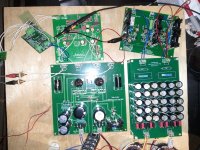
Could you post some detailed pictures of your setup? This would help a lot!
Best,
Oliver
here it is oliver! Thanks.
Attachments
Thanks for the reply noizas. Is the rule of thumb for bandwidth not 5 x clock frequency? Tomorrow I will be able to take a look at it with a better scope.
here it is oliver! Thanks.
Independent of your scope pictures, are there any sound problems with your setup?
Independent of your scope pictures, are there any sound problems with your setup?
yes, i'm getting digital noise on the audio output that comes and goes, most of the time there is silence.
What about your grounding scheme? Did you do it like in my blog?
An externally hosted image should be here but it was not working when we last tested it.
Thanks for the reply noizas. Is the rule of thumb for bandwidth not 5 x clock frequency? Tomorrow I will be able to take a look at it with a better scope.
Hi robots,
there we are talking not about 5x clock rate (MLCK), but about 20 x byte clock (BCK) frequency, as you want to see BCK trace on your scope, not MLCK
Concerning this multiplier, there are Fourier transformation rules - rectangular type signal consists of main sinwave and many of harmonics (repetative frequency sinwawes).
So if you need to transmit, receive or observe rectangular signal you need devices and cables with bandwith which can "handle" some quantity of harmonics also, else you will have distortion.
yes, i'm getting digital noise on the audio output that comes and goes, most of the time there is silence.
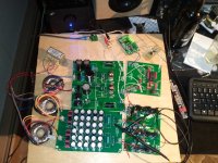
Does your I2S to TDA1541 come from Twisted Pear transceiver directly or through the chip, connected in between the TDA1541 pcb and Twisted Pear transceiver?
It looks like disconnected in picture, but what is purpose of it? Is it some buffer? Maybe here is the problem?
Did anyone have yet the opportunity to to an AB comparison between this DAC and any others? I would like to know how it compares to
DIY-favorites, like buffalo etc.
Commercial competitors, e.g. weiss, benchmark dac1, audio note, etc
Anyone?
Do we have a 'reference dac' on our hands?
I don't think we can improve the main DAC and power supplys much, if any....
IMO the only area of improvement may come in the future with advancements in USB to I2S conversions options...
Every time I turn this thing on it amazes me.
Looking at the 'ultimate' thread, there is much one can do differently, but given the current concept, I think one area for improvement can also be the I/V and output section...
But obviously there are so many different concepts that are around (also commercially used). I just wanted to know how far this is from the world's "reference" class:
- TDA1541-based: The ZANDEN
- All chips: Weiss (ess-based), benchmark dac1, audio aero (DSP based), Theta Gen8 (dsp-based)
Where do we stand? Has anyone done a shootout with (rich) friends yet?
What about your grounding scheme? Did you do it like in my blog?
An externally hosted image should be here but it was not working when we last tested it.
Hi robots,
there we are talking not about 5x clock rate (MLCK), but about 20 x byte clock (BCK) frequency, as you want to see BCK trace on your scope, not MLCK
Concerning this multiplier, there are Fourier transformation rules - rectangular type signal consists of main sinwave and many of harmonics (repetative frequency sinwawes).
So if you need to transmit, receive or observe rectangular signal you need devices and cables with bandwith which can "handle" some quantity of harmonics also, else you will have distortion.
Does your I2S to TDA1541 come from Twisted Pear transceiver directly or through the chip, connected in between the TDA1541 pcb and Twisted Pear transceiver?
It looks like disconnected in picture, but what is purpose of it? Is it some buffer? Maybe here is the problem?
Thanks very much for the tips guys. I solved the problem.
It was just a matter of my cheap sound card not being able to switch modes without a system restart
. 
I should have tried that first
Also, for those interested, I had a look at the BCK today at school with a 200 Mhz scope. It looked normal. 12 Mhz BW is definitely not enough for that signal.
Hi Studiostevus:
Do you have any pic for us about your Pedja Rogic i/v stage?
Thank you.
Here is the pedja rogic diamond i/v stage in operation
An externally hosted image should be here but it was not working when we last tested it.
Here is the pedja rogic diamond i/v stage in operation
An externally hosted image should be here but it was not working when we last tested it.
Is this that on i attached?
Attachments
Last edited:
Oliver, looking at your current setup, it seems you are using both the X2 for USB input and the Twister Pear + buffer for SPDIF input. These seem to be powered from the same regulator. As they have different clock speeds, there will be noise on the power lines from the X2 when the TP is used (and the other way around).
Wouldnt it make sense to add a relay to switch power to EITHER X2 or TP (based on the same switch used to switch the I2S signal), so that only the one you use is getting power?
Wouldnt it make sense to add a relay to switch power to EITHER X2 or TP (based on the same switch used to switch the I2S signal), so that only the one you use is getting power?
Oliver, looking at your current setup, it seems you are using both the X2 for USB input and the Twister Pear + buffer for SPDIF input. These seem to be powered from the same regulator. As they have different clock speeds, there will be noise on the power lines from the X2 when the TP is used (and the other way around).
Wouldnt it make sense to add a relay to switch power to EITHER X2 or TP (based on the same switch used to switch the I2S signal), so that only the one you use is getting power?
What you see is the 1st setup with both I2S converters. I hope that i finish my external Tube PSU this weekend.
If i have power again
i will test different power connections with the regs.BTW, what are the three pots for on your I/V stage?
I need a +15V voltage for the bias current (the section on the right, which injects 2mA current into the TDA1541a to counteract the -2mA offset the chip usually has). So the 15V is taken from the 19V supply via a lm317 based regulator. The first of the pots regulates the 15V voltage.
The other 2 are used to set the bias current itself (generated from the 15V supply via a FET) to EXACTLY 2mA.
The other 2 are used to set the bias current itself (generated from the 15V supply via a FET) to EXACTLY 2mA.
This DAC sounds amazing! I've spent the last week rediscovering my whole music collection. The detailed highs are incredible! I really wasn't expecting such an amazing low end. The way it brings out bass clarity and depth is fantastic. Truly brilliant.
I think it has outpaced my amp. My next project will most likely be a new 2 channel amp. I haven't decided on tube or transistor yet.
It is quite costly to build however. I think the power supply section could be greatly simplified thanks to the Salas shunt regulator. I found no difference at all in my testing on the power supply between polyester film caps and the more expensive polypropylene variety. Each rail could be reduced from 15 caps to 2 or 3 large value caps. Also the number of boards could (should) be reduced.
But at least it looks impressive and you can impress your friends!
Attachments
- Status
- This old topic is closed. If you want to reopen this topic, contact a moderator using the "Report Post" button.
- Home
- Group Buys
- "Reference" TDA1541A DAC with I2S-BUS architecture