Ost,
I am trying to read your sim plots.
I'm struggling.
Could you talk me through them?
A bigger pic with a bit more resolution would help with "reading" those colours.
???? That is the size of the actual output of LT , I did not reduce it any.
I see it good ..

You want bigger... OK (below 1 and 2) and explained....
(attachment 1) is self explanatory , it shows loop response with 3 values of Cdom. 100pF and 60pF (R and B) are fine with 400khz and 650khz unity gain points , they also are at under 100 degrees phase ... leaving over 80 degrees phase margin. With these values , this amp will not overshoot or ring (maybe a little with a capacitive load) , and DEFINITELY will not oscillate.
"G" is a different story , at 20 pF , you have essentially a "oscillator in waiting". It won't self oscillate , but the tiniest disturbance (Xover glitch or squarewave) will create a very hard to damp oscillation with frequencies in the mhz. It's phase is 160+ only leaving 20 as the margin... a NO- NO.
47pF (not shown) is about perfect for conventional miller comp with this amp. 880khz unity gain freq. and about 70+ degree phase margin ... this equates to just a tiny amount of highly damped ringing driving a capacitive load.
(Dadod , your question/statement is answered here ... I used conventional miller to just "make the point" and to use the .step param command - ".step param Cdom 20p 100p 40p")
The TMC in the real amp equates to about 75pF of conventional miller capacitance , resulting in 550Khz unity gain with 80+ degrees margin (rock solid).
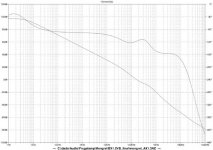
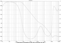
Verbosely , the (second attachment- below) shows the PSRR with a standard power supply setup ( just +/- 58VDC).
RED = shows how the standard 220uF decoupling cap does nearly NOTHING for the audio band , ripple wise.
PURPLE=Probing after the first order cap multiplier , we are looking better.
GREEN = combine the multipliers PSRR with the native PSRR of the amp and you are really doing well - most of the audio band is pushing -100db !! at the amps output. This test only gets better with separate front end /OPS power supplies.
Very good... Ps , are they big enough , Andrew ??
OS
Attachments
Last edited:
1207x905 is very clear and the "colours" are easily visible.
Would my guess for Cmiller at 40pF to 50pF bring the 0dB to ~900kHz and the phase margin to ~85degrees? I can see that the sim predicts that 20pF is way too little.
How does the real amp compare to the sim for phase margin? when around the 80degrees level?
Deep breath, now I 'm going to follow your explanation of what pic2 is showing.
pic2. Perfectly legible.
Why does the amp PSRR + cap multiplier become worse than cap multiplier alone >=16kHz?
Why does the green line suddenly shoot up from ~6kHz?
Is that telling us that the PSRR of the amp has gone >1 for all frequencies above 16kHz?
Can the phase information be used to give us insight into what is happening?
1207x905 is very clear and the "colours" are easily visible.
Would my guess for Cmiller at 40pF to 50pF bring the 0dB to ~900kHz and the phase margin to ~85degrees? I can see that the sim predicts that 20pF is way too little.
How does the real amp compare to the sim for phase margin? when around the 80degrees level?
Deep breath, now I 'm going to follow your explanation of what pic2 is showing.
I have "abused" these in my "barn" , at the 80 degree/800khz+ UG level (which also equals 100/270pF TMC or 47pF CMC ) this amp will push 60 watts of squarewaves into 6 piezo tweeters in parallel for hours. It was ringing slightly and the zoble network became warm. To actually get the zoble HOT, I had to lower the degeneration on the input pair to 22R , which , according to the sim , brings me close to the green plot above.
So , this amp will survive being highly undercompensated. At the equivalent proposed (and built) 100/470pF TMC (=75pF CMC) , the zobel is undetectable thermally and my CRO shows no ringing or even overshoot.
What is nice about this amp , it will work within specs (stable) for equivalent Cdom's of 39p-100p or different combo's of LTP Re's/Cdom's (for example , 47R LTP / 68-100p Cdom or 100R LTP / 39p-68p Cdom). VERY forgiving.
PS . I mistakenly installed 10R Re's at the LTP of one AX and totally fried the Zobel 10R/3W resistor - it was self oscillating at this point ...
OS
pic2. Perfectly legible.
Why does the amp PSRR + cap multiplier become worse than cap multiplier alone >=16kHz?
Why does the green line suddenly shoot up from ~6kHz?
Is that telling us that the PSRR of the amp has gone >1 for all frequencies above 16kHz?
Can the phase information be used to give us insight into what is happening?
That is just a simulation ... would you really see that much high frequency ripple on a real unregulated supply ? This would also depend on the model of the capacitor. Also consider , we did not model the CLC of the real PS , we used ideal 0 impedance/resistance sources for our "sweep".
This does give a "rough" idea of the benefits of using a multiplier.
PS - real world power supply ripple is far more complex than what we can simulate . Will the phase of the ripples be the same between the rails? , what frequencies will the ripple be ? ( many). A complex set of variables as the PS is being modulated by a dynamic load.
To answer the 16khz question ..... at this point the OPS's " un-multipliered" power sources begin to override the IPS/Voltage stage PSRR.
In other words , the output stage is "dirty" and begins to "sour the milk" at HF , exceeding the PSRR of the multiplier. (my best guess)
OS
Last edited:
'morning OS!
Just wanted to let you know the package arrived safe and sound.
Glad to hear that. What is being discussed applies directly to your amps , they are the prototypes... (PB250/AX)
OS
Glad to hear that. What is being discussed applies directly to your amps , they are the prototypes... (PB250/AX)
OS
Cool. I check in with every new post here...
Here is PSRR with series R = .01 L= .05uH and 16,000uF bypass. (below 1)
My "best guess" was right on.
I'm tired, Dadod. done a lot of simming. The EXACT simulation I work on is here : Current Directory: /WEBSITE/MONGREL/Mongrel_Simulations/
"mongrel_ax1.3NC.asc" ... download "mongrelmodels.txt" as well. Run the probe and post. I was just showing global closed loop gain/vs. phase .
OS
Attachments
Os, please don't be angry with me, I am just trying to learn here.
I think that your open loop gain/vs phase does not include TMC influence(not close loop).
First figer is exactly from your sim.
Second is wth R19 connected between R5 and V6. In this case, I think please corect me if I am wrong, opel loop gain/vs phase is showing TMC.
dadod
I think that your open loop gain/vs phase does not include TMC influence(not close loop).
First figer is exactly from your sim.
Second is wth R19 connected between R5 and V6. In this case, I think please corect me if I am wrong, opel loop gain/vs phase is showing TMC.
dadod
Attachments
Dadod:
I am not an electrical engineer, so cannot chime in on the technical issues or simulations.
However, OS has built and tested this amp, to rather extreme conditions I might add, which would kill a lot of other commercially available amplifiers selling for a rather high price, and 'spec'd' with a much higher distortion levels.
In conclusion, I understand your need to understand; however you must remember this has been built and tested and is a REAL amplifier, not only a simulation. And, at the end of the day, that is the goal: a nice amp, NOT a nice simulation.
No offense intended, just trying to clear the air a bit.
not mad ??
Absolutely not mad , Dadod !!! It is good to learn ,I still must do it.
I did sim the OPEN loop gain of the TMC transition somewhere on this thread , and after post #854 - here : http://www.diyaudio.com/forums/solid-state/171159-bob-cordells-power-amplifier-book-18.html#post2390444
" the TMC "poop hits the fan" with Doug Self , B. Cordell , E.Stuart plus all other interested parties / and topics.
I was just very tired.....
OS
Absolutely not mad , Dadod !!! It is good to learn ,I still must do it.
I did sim the OPEN loop gain of the TMC transition somewhere on this thread , and after post #854 - here : http://www.diyaudio.com/forums/solid-state/171159-bob-cordells-power-amplifier-book-18.html#post2390444
" the TMC "poop hits the fan" with Doug Self , B. Cordell , E.Stuart plus all other interested parties / and topics.
I was just very tired.....
Yes it could... but if you look at the AX, Q9/10/11 are thermally coupled on the small heatsink. I have measured 6.21mA from 0 c to 35c / 45 to 80v rails across the 100R resistor. Really tight constant current source !!! Why mess with perfection ??By solid - With reference to post #1517, can Q9 be substituted by a KSC1845?
OS
Last edited:
So far, I'm caught up to post 1441, with good transformer, refurbish-able enclosure and pretty good heatsinks in the 150 watt per channel, worn out, Kenwood KM-993:
Perhaps it needs to be silver?
An externally hosted image should be here but it was not working when we last tested it.
Perhaps it needs to be silver?
Cool....
Strip it down , post some pictures .. let's see how kenwood does it !
Once you do that , it should be easy to retrofit it with DIYamps.
You have, (hopefully)-
1. A nice looking case.
2. A good 40-0-40V+ 500VA trafo (estimate).
3.sufficient thermal solution (HS) to dissipate 300W.
4.input/output hardware (jacks/terminals) , not too much drilling.
You would want to ditch the main power supply caps , they are most likely at the end of their life. Cheap phenolic boards , bye-bye (after you have them photographed).
In the end , you could most likely make a 120-150w DIY amp out of it for 50-75$ TOTAL. NO "hackjob" , make the PCB's to fit the unit, output trannies to use the original holes , etc.
PS - Ebay or street unit ???
OS
- Status
- This old topic is closed. If you want to reopen this topic, contact a moderator using the "Report Post" button.
- Home
- Amplifiers
- Solid State
- The MONGREL (supersym II)