I'm not sure I understand why you would use an Ivy i/v stage after a Vout dac?
I assume its doing balanced to single ended conversion, but is an i/v stage not different to a buffer?
It is not being using as a an I/V converter in this case. Simply an output stage. This is why the input Rs to present a reasonable input impedance to the DAC.
Really it is being used as a balanced filter and buffer with a BAL/SE stage for better common mode rejection.
While it is a VOUT DAC, the output impedance is rather high.
Cheers!
Russ
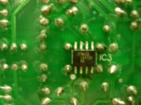
I checked around IC3, I reflowed the joints because they looked kinda crappy. I also looked around at all the joints, some not the greatest but seem ok.
I also checked what I could as far as correct parts. The only thing I question is R13, 14, 15, 16. according to the schematic they should be 2K for stereo and 1K for dual mono. As of now they are 1K. I don't know if this is a problem.
Still the same result, no volume.
The only reason I am not running dual mono is because I didn't know if I could just use + and G from balanced mode without hurting anything.
As I am sure you could already tell I am a rookie at all of this, and I apoligize for being a dumb***. I am learnig very slowly. Only started with diy audio to keep my old brain more active with something I didn't know anything about. What's interesting to me is that I don't even get frustrated or p-off about any problems I have with electronics.(unlike my day job)
Just another learnig experience.
Jim
Attachments
Last edited:
I would look at the IVY. Make sure the relay is activating. The the voltage into the IVY is too low the relay will not activate.
Also check the that relay is not in backward.
If it is not your output will always be shunted to GND.
One other note. When using the IVY you can short the output caps on the Opus. I usually omit them and just use wire jumpers from clipped resistor leads or such. You will get better results this way. I highly recommend it.
Russ, I finally got back to working on this. After closer inspection I believe you were correct with your first diagnosis, the relay had 1 leg not connected. I desoldered it and it had a broken leg, I suppose it was me being ham handed.
I will order a replacement and post results when replaced.
Thanks again for pointing me in the right direction.
jim
Hi, I've just gotten my Opus up and running and wanted to express my thanks to Twisted Pear and all those who posted questions and pics of their builds. I now need to get it into an enclosure with proper jacks but I tried it out by clipping the positive outputs and a ground to my headphones, and it drives them at a very nice level.
The most important parts:
-It was easy to solder, thanks to the wonderful tinning. Thank you so much for that, I've assembled projects which caused a struggle along these lines, so what a breath of fresh air to find something which offers ease...
-I didn't want to stop listening to music even though I was exhausted from a very long day. And I didn't want to skip to the next song; I was trapped listening to music, tapping my toes with a silly smile on my face. And this is before using it with speakers, or even testing it against other units...looks like a winner to me!
Thanks again.
Hi
I'm reading this thread and find the Opus dac and WM8804 receiver module very interesting.
I've readed the WM8741 and WM8804 data sheet. But I'm not a digital gear geek.
To help me to better understand the data sheet, I have questions.
For the WM8804 in the data sheet, which pin number are for the AIFCONF1, TXS, AIFCON1, AIFCON0 ?
And for the WM8741 in the data sheet, which pin number are for the I2S, DM1, DM0, MUTEB, MODE, IWO ?
I found those setting, they are the standard setting for a Opus dac module with the WM8804 receiver module ?
WM8804 RCVR
AIFCONF1 - HI
TXS - HI
AIFCON1 - LO
AIFCON0 - HI
OPUS DAC
I2S - HI
DM1 - LO
DM0 - LO
MUTEB HI
MODE LO
IWO - HI
All Others - Not Jumpered
Thanx
Paul
Last edited:
Hi
...
And for the WM8741 in the data sheet, which pin number are for the I2S, DM1, DM0, MUTEB, MODE, IWO ?
...
Thanx
Paul
Those refer to the old (no longer available) board based on the WM8740. Take a look at the TPA website for the latest boards based on the WM8741
Hi
But for the WM8804 in the data sheet, which pin number are for the AIF/MS, TXSRC, AIFCON1, AIFCON0 ?
In the TPA website, the wm8804 receiver module manual there are the setting.
AIF/MS - HI
TXSRC - LO
AIFCON1 - LO
AIFCON0 - HI
I think that it good to understand a bit the data sheet before doing the wm8804 receiver and Opus dac modules wiring.
Thanx
Paul
Last edited:
Take a look at the schematic: http://www.twistedpearaudio.com/docs/digital/wm8804_schematic.pdf and look for SW1 and compare with photo: http://www.twistedpearaudio.com/images/digital/wm8804.jpg
Hi
So, to be sure I understand ok.
To correspond to the data sheet, the pinouts for those settings on the WM8804 chip for the the wm8804 receiver module are :
AIF/MS - HI --- are pin 1 on the WM8804 chip (SLK)
TXSRC - LO --- are pin 5 on the WM8804 chip (CSB/GPO1)
AIFCON1 - LO --- are pin 2 on the WM8804 chip (GPO0/SWIFMODE)
AIFCON0 - HI --- are pin 5 on the WM8804 chip (SDOUT/GPO2)
Is it correct ?
Thanx
Paul
Last edited:
Can you give more detail? what is connected to the OPUS, is the squeal there with or without music playing. Gnd problems will sound more like a hum.
I use a pc or laptop usb, then connect the dac to one of two headphone amp, any combination gives the same result. Its not grounding hum, I have had that numerous times, its a digital squelch sound.
Its there with no music playing.
Maybe some EMI from a clock source? This can happen if the cable routing is not ideal.
Hi Russ,
cabling is quite minimal check it out on post #1759
http://www.diyaudio.com/forums/twis...gning-simple-balanced-dac-36.html#post2162324
What Im wondering is if the usb input on the dac is touchng the chassis grouns, is this ok or should I create a clearance and isolate them? Bar that I dont know how I would change the cabling routing. Do you think shorter wires would make a difference?
- Status
- This old topic is closed. If you want to reopen this topic, contact a moderator using the "Report Post" button.
- Home
- More Vendors...
- Twisted Pear
- Mr White's "Opus", designing a simple balanced DAC