hmm, just now I read about experiences with broken D3a and C3g, new right out of the box
I have noticed certain people who used D3a extencively suddenly stopped using them
may be best to just use some of the C3g I have, and be prepared for surprices
I use the D3A extensively and have not encountered any "broken" ones out of the box, but if they are suddenly unpopular that is fine with me..

It is a very high transconductance type and the variability from sample to sample is significant - which can present a problem if you do not know how to design for that.
Note that given the relatively high transconductance of the C3G these same issues will also apply.
Last edited:
I use the D3A extensively .......
ah, ok,
yeah, just yesterday I read that you have made a really special 300B PP, ages ago
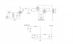
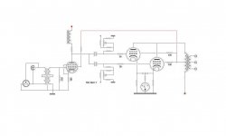
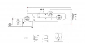
No, not quite.. The grid bias resistor for each tube goes to the wiper of its respective bias pot. The bias pot usually will have a resistor to ground from one end, and possibly one (optional) on the other to the bias supply.
Edit: The better of the two schematics just disappeared. Above comments were directed at the second schematic..
The one left will not allow you to adjust the balance at all, and also is not a safe choice if the wiper goes intermittent - you'll lose both output tubes and possibly the OPT as well. In addition the balance pot is supposed to affect just the bias and not the drive to the output tubes. You still need the two independent grid bias resistors and all of the bias adjustment circuitry is supposed to be out of the direct audio path.
Keep trying!
The grid bias resistor for each tube goes to the wiper of its respective bias pot. The bias pot usually will have a resistor to ground from one end, and possibly one (optional) on the other to the bias supply.Edit: The better of the two schematics just disappeared.
Above comments were directed at the second schematic..The one left will not allow you to adjust the balance at all, and also is not a safe choice if the wiper goes intermittent - you'll lose both output tubes and possibly the OPT as well. In addition the balance pot is supposed to affect just the bias and not the drive to the output tubes. You still need the two independent grid bias resistors and all of the bias adjustment circuitry is supposed to be out of the direct audio path.
Keep trying!
Last edited:
No, not quite..
Edit: The better of the two schematics just disappeared.
Keep trying!
sorry
I will study your reply, and post it again asap

Keep trying!
I have chosen to show two versions in the same schematic
how can a simple pot be so hard
ah, I think I have misunderstood which was 'grid bias resistor', or read it wrong like 'bias grid resistor'
Attachments
I have chosen to show two versions in the same schematic
how can a simple pot be so hard
Still got a little more work to do..
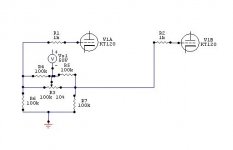
Again bias resistor say 150K from grid of output tube to wiper (center pin) of pot, resistor to ground from one end of pot. Resistor (or direct) to bias supply from other side of pot. Once you've got this conceptually you can make it safe against intermittent wiper contact by adding a 100K resistor from the wiper to the most negative side of the pot. At the tube there will be a grid stopper, the aforementioned grid bias resistor and one coupling cap, and nothing else..
I read your describtion like this
By Jove, I think he's got it!
YES!


hmm, maybe I would be wiser to let this 'die a sudden death'
and just build a SS power amp driven by Broskie's new balanced Aikido
but to me its also about learning, and interesting
maybe it will be built, maybe it wont, I dont know yet
anyway, regarding ultra linear
its my understanding that its also a kind of feed back loop
and why it lowers distortion
half triode, half pentode
so, my question is
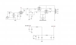
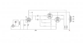
will it be possible to load the driver tube from OPT UL tap ?
marked in read
choke load added too
and just build a SS power amp driven by Broskie's new balanced Aikido
but to me its also about learning, and interesting
maybe it will be built, maybe it wont, I dont know yet
anyway, regarding ultra linear
its my understanding that its also a kind of feed back loop
and why it lowers distortion
half triode, half pentode
so, my question is
will it be possible to load the driver tube from OPT UL tap ?
marked in read
choke load added too
Attachments
hmm, I guess not
if it really was that simple, someone else would have done it a long time ago
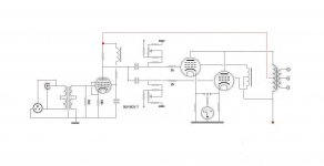
but there is something about a resistor arrangement, making it possible to UL load a pentode driver
not sure, but maybe i could be coupled with the choke load
hmm, there was mention of a cap, somewhere
but where ?
any suggestions
whatever, just now seen one integrated pushpull with KT120
and a very expencive amp
well, someone must think its worth it
if it really was that simple, someone else would have done it a long time ago
but there is something about a resistor arrangement, making it possible to UL load a pentode driver
not sure, but maybe i could be coupled with the choke load
hmm, there was mention of a cap, somewhere
but where ?
any suggestions
whatever, just now seen one integrated pushpull with KT120
and a very expencive amp
well, someone must think its worth it
Attachments
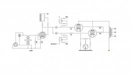
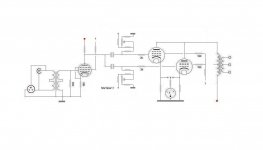
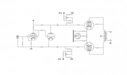
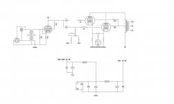
Your UL tap feedback to the driver screen grid in post #92 is making for positive feedback. With a P-P setup, these fdbks can be crossed over to give negative fdbks. Generally some attenuation of the fdbk will be required too. And the screen grid is a low impedance besides. Usually the screen grid presents a non-linear impedance as well, but some tricks can be used to bring that under control (linearize) by making the screen grid voltage "track" at some ratio to the plate swing.
Another way would be to move the feedback link up top to the driver inductor/plate load resistor connection. Becomes anti-bootstrapped "E-linear" mode. Or UL "Schaded" outputs.
Another way would be to move the feedback link up top to the driver inductor/plate load resistor connection. Becomes anti-bootstrapped "E-linear" mode. Or UL "Schaded" outputs.
Last edited:
- Status
- This old topic is closed. If you want to reopen this topic, contact a moderator using the "Report Post" button.
- Home
- Amplifiers
- Tubes / Valves
- Kt-120 ?