Hi guys,
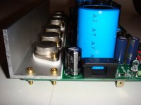
"I find it fascinating that hotzman has soldermask covered boards and I'm curious what he paid for them. I find they look much better than the tinned ones. "
The price per unit is 20 Euro~27 USD! I ordered six pieces of which I left with two.
Likely that the price may be better for a larger amount but do not spend very much!?
Hotzman
I wish you luck. If you have put everything on its right place, it is nothing to worry about.
I recommend you to use a variotransformer.
Connected to a loadspeaker the amplifier start playing long before you reach the max. main voltage from your wall.
Eivind Stillingen
I wish you luck. If you have put everything on its right place, it is nothing to worry about.
I recommend you to use a variotransformer.
Connected to a loadspeaker the amplifier start playing long before you reach the max. main voltage from your wall.
Eivind Stillingen
Jacco
Yes, I admit that I sometimes get a little overzealous in getting on towards the ultimate goal in terms of building the Goldmund clone. The reason I chose to mount capacitors from the drain to the heatsinks, were a try to draw a conclusion from what you wrote in # 1470, and what you have written about this issue in # 1174.
In this latest post you wrote to another member: In case you run into Stability issues, ground the heatsink and solder the C's at the drain to the heatsink (In The Hitachi Appl. Note, btw).
I interpret your statement about this in those two posts to mean, that the capacitors from the drain to the heatsinks were preferable to capacistors from the drain to common GND
Capacitors C and the value of this, 10nF, is not original from Goldmund, but something Alex has added on "his own expense". I chose to stick with Hitachi Appl. note (1000pF).
I understand you so, that I do not listen to your advice and therefore can not (will?) help. I'm sorry that you perceive me like that. In this case I have tried to interpret, probably a little too fast, your well-intentioned advice. I have the utmost respect for your high competence in this field.
I am eager to learn, but it is important how "teacher" motivates. Here it is that I can speak with a certain "heaviness", because education is my profesjon.
Part of your last response to me is marred by a certain arrogance that I wish was unwritten.
I hope that my little "kick" back do not keep you away from giving good comments and help to me and other not so professionals DIYers.
Your comments regarding drivers for Goldmund was very interesting. Drivers have been a topic in other earlier posts, but focus has been directed only against devices that can operate within safty.That was apparently not good enough. BSS71/74 is now ordered.
Eivind Stillingen
DC Offset Drifting
Hi Eivind,
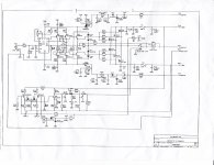
Have a look of the picture on post 960. The R36 (the resistor // to the output inductor) looks like a 22R. Nagy had a value of 0.22R for R36, which I think is too low. The main purpose of the output inductor is to stop the output stage from picking up the HF via the speaker cables, 0.22R will effectively bypass the output inductor.
It may worth a quick test to see if it stop the DC offset drifting.
Cheers, Stanley
The "DC-problems" and my wish to solve it might be a try to "shoot sparrows with cannons".
By the way I have not tried to use BC 546 B for T3/4. I think that will be my last attempt and and then accept the DC level I have. It is by no way dangerouse for my loadspeakers (left better than right).
Eivind Stillingen
Hi Eivind,
Have a look of the picture on post 960. The R36 (the resistor // to the output inductor) looks like a 22R. Nagy had a value of 0.22R for R36, which I think is too low. The main purpose of the output inductor is to stop the output stage from picking up the HF via the speaker cables, 0.22R will effectively bypass the output inductor.
It may worth a quick test to see if it stop the DC offset drifting.
Cheers, Stanley
sng001
Interesting (and sharp) observation. Have checked the picture in post 960 You're right, the value that is written on the resistance is clearly 22 ohms. This means a deviation factor of 100, which is not negligible.
As you say, 0,22 ohm will almost short the effect of the coil. Have checked with several DIY designs, I and have not registered that someone, in the same opposition as R36, use less than 1 ohm (Erno Borbely uses 1 ohm in his DC 100)
When it comes to resistor on the opposite side of the coil, I find no correlation with the BOM list . I read the colors yellow, purple (?), black, brown, brown and orange (?) = 4.7 kohm. Could it be R 19 in the protection circuit?? BOM list says 3.3 Kohms? Thats the closest I could come.
If that's the case, and for me the security circuit works well, I will not worry about possibly changing R 19.
In the case of C 27 (15 nF), the deviation from 10 nF in the BOM list is not
of great importance , I assume???
Eivind Stillingen
hey the purpose of the output inductor resistor is to damp any ringing the coil may create at high frequencies. normal rule of thumb to make value at least twice the minimum value of the intended load. also make sure you use a device that does not exhibit any inductive of its own. I only use good old fashioned carbon 3-5watt and use it as a former for the inductor. wirewound or metal film is not really suitable for this. in fact the best results for high speed MOSFET dvices such as this work best with an all carbon resistor set. on numerous occasions I have come acroos people/DIYer's that change resistors in old equipment such as valve amps or tuners then wonder why they no longer function well or in the case of tuners at all. been watching this project thread with interest. understand as told to me prior post dunno the number its about "the attention to details" not too sure but think some or most of the resistors used on these amps are metal film. whereas I would not do this.
I have been doing reseach into Mosfet devices for audio for over 20 years. had a client who borrowed a design prototype from me years ago to compare to a musical fidelity and a Krell despite my asking him to return it some weeks later he only wanted to give me cash!!! not the unit so think building high quality audio is the norm for me. can someone clarify the used resistor set for this out of curiousity
I have been doing reseach into Mosfet devices for audio for over 20 years. had a client who borrowed a design prototype from me years ago to compare to a musical fidelity and a Krell despite my asking him to return it some weeks later he only wanted to give me cash!!! not the unit so think building high quality audio is the norm for me. can someone clarify the used resistor set for this out of curiousity
I would be nice to know the bandwidth/resonant freq. of that L/R combo to see what it should be....
According to this... CalcTool: RLC or LC circuit calculator
the .22R/2uH has a limited bandwidth (17Khz). I use 10R/1.5-2UH in my amps (better BW - 800k) since the only purpose is to attenuate RF at the OP. (absorbed by speaker wire , etc)
So , by all reasoning ... .22R/2uH IS WRONG.
EDIT: unless ,in the case of the goldmund , the limited BW is there to accommodate RF created from WITHIN the amp.
OS
Last edited:
Thank you arthur for your post. It answers a lot of questions and raises some more...
ostripper,
I have found this information about amplifier stability:
Elliott Sound Products - Audio Power Amplifier Design Guidelines
ostripper,
I have found this information about amplifier stability:
Elliott Sound Products - Audio Power Amplifier Design Guidelines
Speaking of CLR calculations, does anyone remember a Tektronix CIRCULAR Slide Rule like marked calculator for RCL circuits, does anyone have one that a photo pdf can be taken? It was a super good tool in its day... I loved it, I had 2 but they got lost in the life somewhere...
All the circuit he provide is correct as in real Goldmund 9.2
Shame Nagy isn't around to see the power devices type/number used in the 1/2 priced, and 1/3d lower power model.
Didn't that GM brochure state that the 250W monaural used the same circuitry as the 9.2 ?
=> R95/R96 = 2k2 ( or 1k8/100V)
http://ouir.ch/generated/datenblaetter/produkte/1779_3_Goldmund_Mimesis_9.pdf
Speaking of CLR calculations, does anyone remember a Tektronix CIRCULAR Slide Rule like marked calculator for RCL circuits, does anyone have one that a photo pdf can be taken? It was a super good tool in its day... I loved it, I had 2 but they got lost in the life somewhere...
It's in here, somewhere ....
Slide Rules for sale on-line! Sphere's Circular Slide Rule Page
Cliff,
Kris just asked for images, to make one himself with a couple of CD's.
Like this :
http://classictek.org/images/stories/Articles/assorted_material/Tek_Circuit_Computer_1961.pdf
http://sliderulemuseum.com/HSRC/58111.jpg
http://cgi.ebay.com/VINTAGE-TEKTRONIX-CIRCUIT-COMPUTER-1961-INCLUDES-BOOK-/190509192793
(oh dear, i just enlisted in the old fart brigade)
Last edited:
- Home
- Amplifiers
- Solid State
- The Very Best Amplifier I Have Ever Heard!!!!