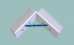
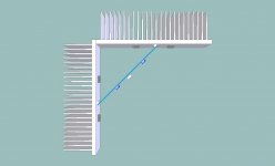
Andersonix, I appreciate your ideas, and help. I've decided to go with what I thought your first idea was. Rather than wack up an 8X10 like the major design depecticted, I should just add a 4" section like your first pic suggests. Also, rather than do-it-myself, I went ahead and ordered a 4" peice to mount like your first pic. Thanks for the idea, but, I need a few days for UPS to deleiver before I have any measureable results... In the mean time, How should I fix the backside piece to the frontside piece? I think maybe 5 bolts front to back (1 in the middle) and some A.S.5?
Andersonix, I appreciate your ideas, and help. I've decided to go with what I thought your first idea was. Rather than wack up an 8X10 like the major design depecticted, I should just add a 4" section like your first pic suggests. Also, rather than do-it-myself, I went ahead and ordered a 4" peice to mount like your first pic. Thanks for the idea, but, I need a few days for UPS to deleiver before I have any measureable results... In the mean time, How should I fix the backside piece to the frontside piece? I think maybe 5 bolts front to back (1 in the middle) and some A.S.5?
Arctic Silver Thermal Adhesive - HeatsinkUSA, LLC Store ?
just a thought
")
I have the Sonus Faber Grand Piano Domus, bloody 4 ohm, and I still did not understand where I should stand. Maybe it's not such an extreme case.
I have the most standard ever F5 (no complains), would like to try the balanced (I tried one bridged channel).
But I am not sure if for me it's better to go with a parallel mosfet or the balanced. I have a balanced source, and I would like to use it as balanced. My case is not extreme, although I could not find on the network the impedance chart of my speakers, and I was always lazy to measure that (I have to kick out the family to put test tone in my speakers)
Any thoughts ?
D.
So I made it. Toshiba mosfet, 0.22R degeneration resistor, degeneration trick on the jfet and no termistors.
13 V rails and 2.8A bias per mosfet.
Did not sound good. Low volume is fine, but you can hear the clipping (guess voltage) as soon as you increase the volume a bit.
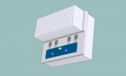
I have to say that I did not miss the thermistors, as the bias is less nervous without, but I had no case around. I am using the Conrad M151-350 as heatsinks and the ALOX pads for the Mosfet.
The ALOX pad are a bit small for the Toshiba Mosfets, as they are for TO247, but they cover all the metal part. Only a couple of mm close to the pins remain with no contact.
Next I will increase the voltage with a variac to see what's the minimum voltage that makes sense.
I did a bit of research on my speakers and I found this:
"The Grand Piano DOMUS is tuned to 36Hz. I agree with Sonus faber's nominal impedance rating of 4Ω, though it does dip below 4Ω from 89Hz-172Hz, with a minimum value of 3.5Ω at 107Hz. But the impedance phase angle remains remarkably benign across the full audible range. Any amp comfortable with a 4Ω load should have no trouble with this speaker. The Grand Piano DOMUS' sensitivity measured approximately 89dB/2.83V/meter."
So my low impedance speakers are not such an extreme case, i guess.
Bye,
Davide
Great. Except "Did not sound good. Low volume is fine, but you can hear the clipping (guess voltage) as soon as you increase the volume a bit." You seem to have a handle on what's happenning. I agree, at around 9-10 volts your probably starting to clip without having run out of ClassA current yet. Voltage limited
That is why I'm looking for a compromise voltage like 15-19V rails. Any less and you can only effectively drive low Z speakers. I'm also affraid of the Capacitance effects of lower D-S voltage on the output devices if I go as low as 12-13V. Any more Voltage and you burn to much static/idle power when you are driving low Z loads. I think I would like to try 16V rails with 2A bias if I can. I'm shooting for +and- 19V or so with a 2X15Vrms xfrmr/ch on the first attempt.
Another factor is, I have nothing to compare to. It would be good if I had a std F5 and the 2xoutput high biased version to compare to?
I did some more Heat Sink testing recently of the single pair temps and the additional 4" section but I need to post the data and I don't have it with me...
I've explained my reasons for the lower the rail. I am just not ready to plan on 12V rails working good without experimentaion. 1 channel will be burning 120+ watts at idle. That's just about enough for me. 30 Watts/device is also enough. Any more bias than 1.3A with 24V rails and you'll be endangering the life of the components and or requiring more heat sink. If you look through the other 15 F5 threads you will find reports of builders who have completed amps with the dual outputs and std rail voltage and bias.
I'm looking to get a few more amps out, in class A, and I don't need all that much voltage out.
I'm looking to get a few more amps out, in class A, and I don't need all that much voltage out.
Another factor is, I have nothing to compare to. It would be good if I had a std F5 and the 2xoutput high biased version to compare to?
This is the reason why I have also a textbook F5. I'll increase the voltare to 16V and listen again.
D.

Typically, in a general sense, you might be correct
What if you have a 2 ohm nominal speaker system?
What if you are driving a system with efficiency/sensitivity over 100db/w/m?
What if it is a line array?
20V out into 8 ohm = 25wrms 12V out into 2 ohms = 36wrms
What is the efficiency of your system? A system with well over 100db/w/m is 2X? 4X? 8X more efficient than typical systems?
Line array's, well just double that output again due to the doubling of the wavefront from line speakers.
Wimpy? A hamburger-loving character from the Popeye cartoon? "I would gladly pay you on Tuesday, for a hamburger today"?
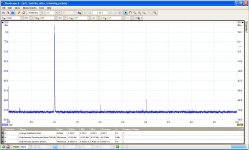
So, I am running with the variac, and brought the voltage arounf 17.5 V. The maximum I can go with this variac.
I kept 2.7 A in the mosfet. Well...impressive. I also did a bit of tuning with the spectrum analyzer. The goal was to have a distortion spectrum similar to the one reported in the F5 article. I have to say that Toshiba mosfet go down in distortion of an order of magnitude.
I am really thinking of backfitting a pair of Toshiba in the reference amp.
Maybe sometime Partick (EUVL) is a bit grumpy, but he knows what he is doing. His note on the complementarity of the mosfet were very useful.
Guess I will have to go to buy some transformers :-(
I will next try the toshiba with 24 V and reduced bias.
D.
Just think, if you put the dual output cfg and my low Z target operating points, together with Patricks balanced version, you could have quite the capable high power balanced amp omptimized for 3-4 ohm speakers
Probably need to monoblocks but I think the low Z bis needs amps sitting next the speakers anyway.
Probably need to monoblocks but I think the low Z bis needs amps sitting next the speakers anyway.
- Status
- This old topic is closed. If you want to reopen this topic, contact a moderator using the "Report Post" button.
- Home
- Amplifiers
- Pass Labs
- F5 For Low Z Loads ?