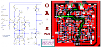
I am redraw the schematic from the PCB and hand writes. Its coming from this discussion (when not redraw yet): http://www.diyaudio.com/forums/solid-state/183997-solid-state-amplifier-obsolete-3.html
This one is very good and stable, I am using it for long time with various output stages and usually results in great sounds.
This one is very good and stable, I am using it for long time with various output stages and usually results in great sounds.
Attachments
results in great sounds.
yes
because it is designed according to low memory distortion rules
")
@MIIB.
The second 2sc3355 is used to boost its gain. When look at BC557, they has almost constant Vbe at low current, then it is good to keep BC557 in very low current operation, it also will draw less input current. Not as low as JFET.
@Pidamiecki
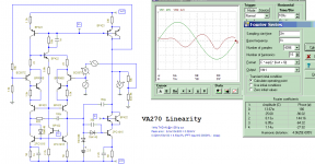
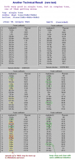
Umm, what is low memory distortion rules? Yes it does has low distortion. Here is some comparison. But I am not following very low distortion is best, output stages has major effect too.
other VAS coming from there: (Iam also post my new output stage there)
http://www.diyaudio.com/forums/solid-state/183144-different-cas-typology-very-low-thd-7.html
The second 2sc3355 is used to boost its gain. When look at BC557, they has almost constant Vbe at low current, then it is good to keep BC557 in very low current operation, it also will draw less input current. Not as low as JFET.
@Pidamiecki
Umm, what is low memory distortion rules? Yes it does has low distortion. Here is some comparison. But I am not following very low distortion is best, output stages has major effect too.
other VAS coming from there: (Iam also post my new output stage there)
http://www.diyaudio.com/forums/solid-state/183144-different-cas-typology-very-low-thd-7.html
Attachments
@Pidamiecki
Umm, what is low memory distortion rules? [/url]
Please read whole links
at this thread
http://www.diyaudio.com/forums/pass...adin-no-memory-distortion-ultimate-aleph.html
and this Memory Distortion Philosophies - Part 8 : More tests
general:
cfp input + cascoded VAS = low memory distortion
around the input pair you have a second set of transistors...What to they do...and could they work around a set of jfets...
I am simulating it with j117 replacing BC557, and distortion become 0.00006%@1kHz, 0.0017%@20kHz and still very stable when clip.
Thanks padamiecki,
Please read whole links
at this thread
http://www.diyaudio.com/forums/pass...adin-no-memory-distortion-ultimate-aleph.html
and this Memory Distortion Philosophies - Part 8 : More tests
general:
cfp input + cascoded VAS = low memory distortion
I have read them, may be too fast, but it really makes me think that may be memory distortion is true. When I, first placing cfp input, I am hoping it will have constant Vbe and higher gain, because using darlington will also add second Vbe.
I am also going to investigate my output stage with memory distortion philosophy, Thanks alot for that infos
.It would be interesting to hear your thoughts on how you find different input stages and VAS sound. How does CFP and cascode change the sound? I guess you have compared this to a standard configuration.
I also find this complex input stage with CFP and cascode to sound very good. I'm not so sure about cascoded VAS. I've posted my findings here http://www.diyaudio.com/forums/solid-state/182095-cascoding-folded-cascode-2.html#post2450431
I also find this complex input stage with CFP and cascode to sound very good. I'm not so sure about cascoded VAS. I've posted my findings here http://www.diyaudio.com/forums/solid-state/182095-cascoding-folded-cascode-2.html#post2450431
It would be interesting to hear your thoughts on how you find different input stages and VAS sound. How does CFP and cascode change the sound? I guess you have compared this to a standard configuration.
I also find this complex input stage with CFP and cascode to sound very good. I'm not so sure about cascoded VAS. I've posted my findings here http://www.diyaudio.com/forums/solid-state/182095-cascoding-folded-cascode-2.html#post2450431
Nice to hear that, nelson ,you also comparing quality by its sounds .
It is long story. I am using some different input stages and VAS in the past.
My first version is simple differential pair with 100mA bias VA to drive single EF directly. This one is my first good sounding amplifier. Then some people very interested in my amps. But the later version is worse with the same EF, this is first time I realize that VAS has the differences too, not just same function to amplify the voltages.
Until I have this VAS, and 2SC3355 or SS9018H/I really help in stability and its performance. Before using them, I have many compensator circuitry to prevent oscillation, and that 150pf is 470pf that time.
I have using cascoded VAS before it because my amps need high voltages, and also using video CRT transistors, some people says that video transistor not good for audio, but I found it nothing wrong.
I am using cfp input when start my V+I amplifiers. That I think it need more linear input stages. I cascoding it to get constant Vce at around 7V, and I see some amplifier using this too. I am impressed in first test, and improving it until now.
If that my VAS really that good (as low memory distortion is true), may be my new VAS will not better than this.
Here is my example if anyone want to hear it. Beware may be it is lttle exciting
.EDIT:
I forgot it, any changes from A872E to BC557B/C or C3355 to S9018H need some different TO-92 legs arrangement in PCB. 2SA/2SC has ECB and BC/SS CBE, see the datasheet for detail. IC hole matrix PCB is usable.
Attachments
Last edited:
Member
Joined 2009
Paid Member
I read over the memory distortion stuff recently, it was quite interesting indeed. But there was one thing that I couldn't work out to my satisfaction and that was the listening test results. From what I can see all the comparisons were between simple topologies designed without memory distortion in mind and more complex topologies designed to reduce memory distortion. BUT the more complex topologies were vastly superior for other reasons not connected with memory distortion considerations at all - adding CFPs improves linearity with localized feedback, adding cascodes has similar advantages - with big increases in OLG etc. I don't see how any tests based on these structures can separate out the obvious improvements in linearity from improvements in memory distortion. For me it remains an unproven case. And since I prefer simpler topologies for all sorts of reasons I haven't found a justification for this type of front end.
But the listening tests do at least confirm that the technically better topologies can be heard to sound differently.
But the listening tests do at least confirm that the technically better topologies can be heard to sound differently.
Last edited:
I read over the memory distortion stuff recently, it was quite interesting indeed. But there was one thing that I couldn't work out to my satisfaction and that was the listening test results. From what I can see all the comparisons were between simple topologies designed without memory distortion in mind and more complex topologies designed to reduce memory distortion. BUT the more complex topologies were vastly superior for other reasons not connected with memory distortion considerations at all - adding CFPs improves linearity with localized feedback, adding cascodes has similar advantages - with big increases in OLG etc. I don't see how any tests based on these structures can separate out the obvious improvements in linearity from improvements in memory distortion. For me it remains an unproven case. And since I prefer simpler topologies for all sorts of reasons I haven't found a justification for this type of front end.
But the listening tests do at least confirm that the technically better topologies can be heard to sound differently.
I agree with you, I am not so convinced about this 'memory effect' by thermal spikes, the relaxation time of phonons (quantum of vibrations at the semiconductor lattice) are around pico-seconds, the stored charge transient through internal and external reactances of the physical device, seems to me be the source of this 'memory effect'.
Cheers
Arturo
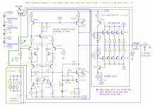
I am already post an example amplifier schematic, that has fb stage switch, V-I knob, and PCB plus schematic of VAS. I don't really know how could this sounds like this, most things are going unproven. I hope someone could reveal it also.
I am using ksp2222a/2907a as mosfet predriver that bump the driver and output with +/-9.2V floating voltages. Those BD139/140 configuration will be close to its function.
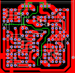
This one I cut it from my amp PCB files. If someone need to use S9018H or S9018I.
I am using ksp2222a/2907a as mosfet predriver that bump the driver and output with +/-9.2V floating voltages. Those BD139/140 configuration will be close to its function.
This one I cut it from my amp PCB files. If someone need to use S9018H or S9018I.
Attachments
I would really like to see more reviews of different topologies, not just simulations and measurements. I know a lot of people here are more interested in the circuits from an intellectual viewpoint, but still...
What does cascoding do to the sound, and is the effect different in the input stage and VAS? CFP, different voltages and currents in VAS and input stage, local vs global feedback, resistors vs active current sources etc. Can we hear those things? How do they sound? Are there different roads to the same goal - an inaudible circuit? Simple is better vs complexity? Some subjectivism please!
What does cascoding do to the sound, and is the effect different in the input stage and VAS? CFP, different voltages and currents in VAS and input stage, local vs global feedback, resistors vs active current sources etc. Can we hear those things? How do they sound? Are there different roads to the same goal - an inaudible circuit? Simple is better vs complexity? Some subjectivism please!
Hi Nelson, I have describe it before at this thread: http://www.diyaudio.com/forums/solid-state/183997-solid-state-amplifier-obsolete-3.html that it has very clean and detail sounds when I test it with some lemay's.
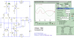
I found something here, very interesting. This is another test, ofcourse it is simulation. According to this, simple VAS really doing wrong way.
Any way, it is not good to leave technical things, because they could reveals what really happened, and simulator do much help without soldering and buying more devices.
And also not good, and really wrong to leave listening test. because it is testing what we heard. Good technical results and sounded bad will not accepted to be claimed as good, but it still bad all according the listening.
Attachments
I am doing some investigation last night, and at least now I understand, why video transistor is exist, and why I got better result with video transistors in my VAS. Also why they always using 2SC1906 for their V->I transfer.
Video V->I amplifier designer could easily see their results differences from their CRT pictures without investigating what really happened, but we in audio need to carefully listening the loudspeaker that it is much difficult. And many audio people will not agreed with anything that different from what they have learned from their books. And the just say that video transistors are bad and avoids anyone using it.
The worst things is coming when any transistors that doing multi tone V->I transfer like amplify voltages here, not being cascoded. May be they are right to call it as memory distortion, as the effect is coming from its varied Vce that affect transiently to transistor transfer characteristics. Also happened to fet family, BJT is better in this case, but both of them doing right if cascoded.
I don't understand your reasoning about that 'memory effect'
Hi Ontoaba,
I really don't understand your points about what you call 'memory effect'. I you do FFT of a 3 tone signal you'll see what's really happens, that is:
the productions are the set of {HT1(i), HT2(j), HT3(k), IMD12(i,j), IMD13(i,k), IMD23(j,k), plus higher order IMD combinations ...} (a big set)
where:
HT1(i) is the set of T1 harmonic production, HT2(j) and HT3(k) the second and third tone respectively, and IMD12(i,j), IMD13(i,k) and IMD23(j,k) ... etc are the IMD products.
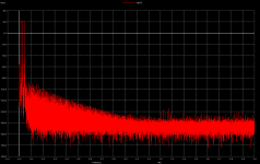
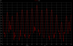
Thats can give 'myriads' (depending on distortion of the amp) of H+IMD products. The first pix show the 3 tones (11,23,43 KHZ) and a region with the productions at it's right. Pix 2 shows a detail of this production and you will find that are populating the BW each KHZ, because 1KHZ is the common divisor of the seed tones. So I think it is an adventurous speculation to explain the harmonic production and it's levels by some 'memory effect'. Also it is real that a less distortive device (or topology) will limit the production BW and levels, but it will occur more or less due to the non linear nature of BJT's.
Cheers
Arturo
Hi Ontoaba,
I really don't understand your points about what you call 'memory effect'. I you do FFT of a 3 tone signal you'll see what's really happens, that is:
the productions are the set of {HT1(i), HT2(j), HT3(k), IMD12(i,j), IMD13(i,k), IMD23(j,k), plus higher order IMD combinations ...} (a big set)
where:
HT1(i) is the set of T1 harmonic production, HT2(j) and HT3(k) the second and third tone respectively, and IMD12(i,j), IMD13(i,k) and IMD23(j,k) ... etc are the IMD products.
Thats can give 'myriads' (depending on distortion of the amp) of H+IMD products. The first pix show the 3 tones (11,23,43 KHZ) and a region with the productions at it's right. Pix 2 shows a detail of this production and you will find that are populating the BW each KHZ, because 1KHZ is the common divisor of the seed tones. So I think it is an adventurous speculation to explain the harmonic production and it's levels by some 'memory effect'. Also it is real that a less distortive device (or topology) will limit the production BW and levels, but it will occur more or less due to the non linear nature of BJT's.
Cheers
Arturo
Attachments
Don't worry I am still investigate it again and again. It is happened when signal starts from zero to specific level. That noise also happened to my VAS too, but it is smaller and reduced in 2uS, while faster simple VAS need more than 10uS to reduce this noise. It is white (flat), and spreads at below 1kHz too.
May be related with DC transient, It is difficult to simulate, my free tina7 user defined signal ability is blocked by free demo version, I can only use PWL macro generator and typing sine step signal in it also impossible.
Added:
You may compare it first by its sounds, the difference is real, and if you need more power you could use high biased HEXFET with current feedback.
Added:
You may compare it first by its sounds, the difference is real, and if you need more power you could use high biased HEXFET with current feedback.
Last edited:
- Status
- This old topic is closed. If you want to reopen this topic, contact a moderator using the "Report Post" button.
- Home
- Amplifiers
- Solid State
- My VAS performance "NEVER LET ME DOWN"