TO-247s just need insulation pads, no nylon screws. Maybe you refer to some chassis screws you miss.
Yes I know, but I need (φρεζάτες)M3
You can check some bias voltages for each stage meantime, check that it generally passes healthy signal, that kind of stuff before you will box it up.
1KHz sine and 1KHz / 10KHz square
Attachments
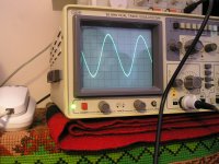
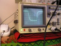
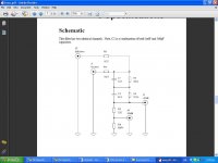
The 1kHz square shows very good Riaa conformity at 1kHz flat point. 10kHz shows it's Lipshitz keeps on cutting HF beyond audio. It takes an anti Riaa filtered signal to check squares different than 1kHz. Did you use an attenuator? What is the test signal's level on phono's input? You can also check the channels balance by watching if you get same amplitude from both channels for same input signal.
The signal is passing thru Iriaa (see pdf) The Iriaa is fed with 200mVThe 1kHz square shows very good Riaa conformity at 1kHz flat point. 10kHz shows it's Lipshitz keeps on cutting HF beyond audio. It takes an anti Riaa filtered signal to check squares different than 1kHz. Did you use an attenuator? What is the test signal's level on phono's input? You can also check the channels balance by watching if you get same amplitude from both channels for same input signal.
The channels level is exactly the same
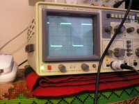
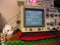
The signal down is from generator and up from salas phono (10 KHz/ 1KHz)
Attachments

Last edited:
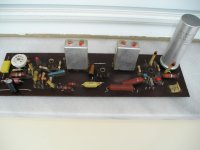
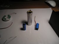
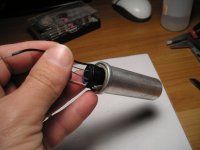
It's my grandfather radio which I have restoration. ERRES KY5953
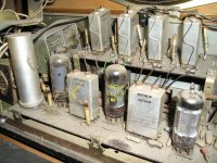
It's tubed right? could you post a photo of inside? surely sounds glorious
")
The signal is passing thru Iriaa (see pdf) The Iriaa is fed with 200mV
The channels level is exactly the same
The signal down is from generator and up from salas phono (10 KHz/ 1KHz)
That one IRIAA has 50kHz pole, so its normal the Simplistic's Lipshitz rounds off the 10kHZ, has no compatible zero beyond the audio band. It takes 100kHz flat bandwidth to see a proper 10kHz square. Channels match, all seem well for now.
You feed from the -60dB (1/1000) output I presume? That would be 0.2mV. If it is the -40dB that would be 2mV. What is the target gain of your version please remind me.
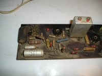
Sorry I have only before restoration. The last one is from PCB after restoration. And yes it sounds very nice but we don't have many radio stations in AM anymore.It's tubed right? could you post a photo of inside? surely sounds glorious
Attachments
56dbWhat is the target gain of your version please remind me.
No, it does not have a special subsonic filter. It relies on the interstage and output capacitor values and their loadings for determining its sub LF response in a system. That is what it will do with the standard 100n interstage and 2u2 output capacitors on a 10kOhm input impedance preamp for example. Would do the same with 22n output caps on 1Meg tube preamp, or with 220n on 100k etc.
Attachments
I solved the problem with temperature; by reduce the current from 2X175mA to 2 X 130mA. Now the temperature is 50C on heat sink and 40 inside the case near the elements. Also I reduced the value of C2 from 15.33nF to 15.10nf. The equalization now is more accuracy and the stage more wide.
But I think that it needs more gain. My old phono has 63dB and the 56dB sounds a little weak. Sometimes I think is better to convert it to MM with 43dB plus low MC pre-pre (total 63db according PDF). Do you believe that will have problem with noise or anything else? My cart is Shelter 501 (0.4 mV)
But I think that it needs more gain. My old phono has 63dB and the 56dB sounds a little weak. Sometimes I think is better to convert it to MM with 43dB plus low MC pre-pre (total 63db according PDF). Do you believe that will have problem with noise or anything else? My cart is Shelter 501 (0.4 mV)
Last edited:
- Home
- Source & Line
- Analogue Source
- Simplistic NJFET RIAA