I'm not sure if we are agreeing or disagreeing. Without a sketch these matters are difficult to describe with words.
It seems to me there are two approaches to this. Lets say we want to take measurements, and also design the system, from a distance of one meter away. Lets say that the tweeter is very shallow with the acoustic center exactly on the plane of the baffle. The woofer is below and has its acoustic center 50mm back.
We can measure both units and their phase curves directly and decide to cancel out 1 meter of air path delay. The phase curve of the tweeter would happen to exactly match its Hilbert transform. The measured phase of the woofer would have excess phase equivalent to 50mm of extra depth.
If we simulate with those phase curves and tell the program that the sources are on the surface of the cabinet (woofer has no depth) we will have an accurate simulation. The extra phase delay in the woofer's measurement compensates for not ascribing any depth to the unit.
Alternatively you can Hilbert transform the individual driver curves and define the tweeter as on the cabinet surface but the woofer as 50mm behind. The results are exactly the same since the 50mm not included in the phase measurement will be calculated by the program when considering the system's geometry.
Most simulation programs consider off axis response by recalculating the relative geometry of the drivers from the different observation axies. 15 degrees up would be some distance closer to the tweeter and farther from the woofer assuming we are rotating around a point between the two. Whether the receeding woofer point is at the surface of the box or 50mm into it will have very little effect and will be within the true accuracy of the simulation, especially since we aren't considering the extra phase shift and rolloff that the 15 degree change would make in the driver's actual responses.
All I'm saying...
David S.
I think we are agreeing as to cause, I think that we just don't agree as to importance.I'm not sure if we are agreeing or disagreeing. Without a sketch these matters are difficult to describe with words.
Yes, as long as in this case the (x,y,z) of the woofer is the same as the (x,y,z) of the tweeter in the software. If the software has a coordinate system for driver position, they must be the same so as to introduce no additional excess-delay difference to the drivers. The 1m point adds the same excess-phase to each driver in this instance. It's essentially simply measured response plus 1m of the mic if set at 1m distance on-axis. The mic has to have the same (x,y) in this case. It's a 2-dimensional setup.It seems to me there are two approaches to this. Lets say we want to take measurements, and also design the system, from a distance of one meter away. Lets say that the tweeter is very shallow with the acoustic center exactly on the plane of the baffle. The woofer is below and has its acoustic center 50mm back.
We can measure both units and their phase curves directly and decide to cancel out 1 meter of air path delay. The phase curve of the tweeter would happen to exactly match its Hilbert transform. The measured phase of the woofer would have excess phase equivalent to 50mm of extra depth.
If we simulate with those phase curves and tell the program that the sources are on the surface of the cabinet (woofer has no depth) we will have an accurate simulation. The extra phase delay in the woofer's measurement compensates for not ascribing any depth to the unit.
Even with a shallow tweeter that may reduce possible error, the model created for the HBT should have a properly tailed lowpass if one is going to assume that the tweeter HBT phase matches the measured phase minus excess-phase. The woofer lowpass could easily be into the noise floor (especially for DIY) and could have some rather unusual response in that area, both due to driver breakup and then adding in noise. The tweeter may extend beyond the measurement system's capability, say a 30K tweeter measured by a 48K sample-rate system (not uncommon). Hence my suggestion to use the manufacturer's curves as they'll be fairly representative.Alternatively you can Hilbert transform the individual driver curves and define the tweeter as on the cabinet surface but the woofer as 50mm behind. The results are exactly the same since the 50mm not included in the phase measurement will be calculated by the program when considering the system's geometry.
This is before considering things such as the window used, smoothing if applied as well as the window time markers.
I'm sure that we mostly agree, except again for importance. If one is working on a first order (or even second order) acoustic response system, then this error can be important. At least in my opinion.Most simulation programs consider off axis response by recalculating the relative geometry of the drivers from the different observation axies. 15 degrees up would be some distance closer to the tweeter and farther from the woofer assuming we are rotating around a point between the two. Whether the receeding woofer point is at the surface of the box or 50mm into it will have very little effect and will be within the true accuracy of the simulation, especially since we aren't considering the extra phase shift and rolloff that the 15 degree change would make in the driver's actual responses.
All I'm saying...
David S.
My point is that all of the above mentioned uncertainly, all of it, can be totally eliminated. Time marker issues? Moot, even with differing start time markers, since the only concern is the summed responses, measured and modeled. Drivers in the noise floor? Moot. Window used? Moot. Questions about the HBT due to tails or lack thereof? Moot.
That's all I'm saying here. Why not go for it when it's so easy? It simply leaves no doubt. Then one need only be concerned with the other issues that will remain in both cases.
Dave
Yes, this is one issue that was discussed with Jeff. It came down to two things, the GUI real estate needed to add it and the complexity of the program by that time. Series traps in parallel with a driver aren't an issue, but parallel traps in series are. I was a bit surprised, though at the low level of error that this introduces, at least in my experience. the higher the Q the more important I think. After starting with the PCD, I always eventually moved the results into CALSOD for final optimization, as it includes the inductor gauge in the process. I'm not aware any other software that does this, except SpeakerWorkshop by what you say, even the latest commercial offerings, at least of reasonable cost. LEAP probably does this, but at high cost.One problem I have with PCD is that it doesn't support adding the series resistance for coils in the "additional" crossover components part. Since the bass section of my crossover is mostly (this latest sim did have an added series coil) affected by Notch filters, the PCD doesn't give anywhere near accurate results due to it assuming that the inductors are perfectSpeaker workshop does allow me to put in the series resistance of the inductors and it gives a much better correlation... PCD allows me to find a starting point for the notches, but it needs to be tweaked in SW to get something that approaches reality...
Yes, this is quite common. It's a typical method used for non-aligned drivers. The issues are whether or not the correction is adequate (doesn't introduce too much peak or dip above/below Fc) and also what impact this may have in the power response. Keep in mind that off-axis, the response may change dramatically, since the true lobe will likely be pointed up or down. It's importance will vary.One more small question. Is it sensible to move the crossover frequency either apart or overlapping somewhat if it results in the phase matching better?
BTW, if you go through the exercise of accurately creating the HBT models, then with the PCD you can easily investigate just how much change occurs off-axis, due to the crossover only, of course.
An alternate method is to "relax" one or the other slopes. With a woofer, if you have, for example, an acousic 4th order L-R target, relaxing the slope of the woofer up to something like 3rd order will reduce some the group delay so that the phase matching will improve. It's not a perfect solution, but there aren't many that are.
Dave
Thanks Dave,
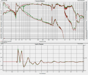
I've had a play in Speaker workshop today with the non-ideal measurements I made recently. The three measurements I have were all taken with the same exact mic position with respect to the speaker (on axis with the tweeter). They are woofers running full range. tweeter running full range. speaker running with crossover in place.
The sim did not line up that well when I put in the current crossover components. However putting in a -ve offset of 1.4cm for the tweeter made a big difference (note I think that this offset is more to do with the fact I didn't zero lock my measurements, than a real offset).
This is using the phase as it came out of holm impulse, I didn't do a hilbert transform to derive the phase from the spl trace.
whilst there are some small errors I think the correlation is excellent (for this particular measurement set). I did have to fudge it a bit as the pad R on the tweeter I had to increase by 0.8 ohms over actual to get the sim to agree with the real measurement..
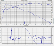
I've also attached a second comparison which is that between actual, sim with offset, and same sim with no DCR in the notch inductor... the error isn't severe but it is noticable! I have to try the same thing in PCD to see how it behaves and compare to the actual and SW sims too.
Note that the woofers curve in the sim is the one with the nearfiled spliced in so that is why the rolloff is different. The error between 1K and 500Hz with the sims is interesting, but as I said I'm using spliced nearfield data so that could well be the cause of that... But it looks like I now have a new way to adjust my sims to get them closer to actual measured results! When using good measurements hopefully the adjustment required will be minimal.
Tony.
I've had a play in Speaker workshop today with the non-ideal measurements I made recently. The three measurements I have were all taken with the same exact mic position with respect to the speaker (on axis with the tweeter). They are woofers running full range. tweeter running full range. speaker running with crossover in place.
The sim did not line up that well when I put in the current crossover components. However putting in a -ve offset of 1.4cm for the tweeter made a big difference (note I think that this offset is more to do with the fact I didn't zero lock my measurements, than a real offset).
This is using the phase as it came out of holm impulse, I didn't do a hilbert transform to derive the phase from the spl trace.
whilst there are some small errors I think the correlation is excellent (for this particular measurement set). I did have to fudge it a bit as the pad R on the tweeter I had to increase by 0.8 ohms over actual to get the sim to agree with the real measurement..
I've also attached a second comparison which is that between actual, sim with offset, and same sim with no DCR in the notch inductor... the error isn't severe but it is noticable! I have to try the same thing in PCD to see how it behaves and compare to the actual and SW sims too.
Note that the woofers curve in the sim is the one with the nearfiled spliced in so that is why the rolloff is different. The error between 1K and 500Hz with the sims is interesting, but as I said I'm using spliced nearfield data so that could well be the cause of that... But it looks like I now have a new way to adjust my sims to get them closer to actual measured results! When using good measurements hopefully the adjustment required will be minimal.
Tony.
Attachments
Last edited:
I want to make a point that I never see come up. I have mentioned it in the past but it never seems to sink in. When we make an on axis measurement we can find the approximate AC by perfroming a HTB on the amplitude data and removing excess phase from the measured phase until the HBT phase matches the measured phase - excess phase. So, say the excess phase sets the AC at 105 cm. 105 cm form where? When we measure on axis we assume that the AC also lies on the axis so we place it at 5 cm behind the baffle on the driver axis, assuming the mic was 1m from the baffle. All this makes sense, on axis. But say we maeasue at 45 degrees off axis. When we find the distance equivalent to the excess phase all we know is that the propagation distance from mic to some imaginary source location (AC45) is X cm from the mic. We can swing an acr and see where it intersects the driver axis but there is nothing to suggest that at 45 degeree off axis the AC should still lie on the driver axis, let alone at the same position as the value found for on axis. If we were to construct an imaginary plane which contained the driver axis and the point of the mic position then about all we can say is that the AC45 is in that plane and in the direction of the driver. But we really can't say much more. The point is that the AC is not a fixed point. It is always nothing more than some imaginary point based on the HBT and excess phase and measurement position.
The real problem is that the sound does not really originate from a point, thus as we move the measurement position around in space the asumption that it does falls apart.
The real problem is that the sound does not really originate from a point, thus as we move the measurement position around in space the asumption that it does falls apart.
An externally hosted image should be here but it was not working when we last tested it.
Hi John,The real problem is that the sound does not really originate from a point, thus as we move the measurement position around in space the asumption that it does falls apart.
An externally hosted image should be here but it was not working when we last tested it.
Yes, I've only occasionally considered this and suspect that the larger (deeper) the driver, the more it will vary in this aspect. It surely does complicate the issue. Since the AC is dependent on the radiation from all points on a driver and their inherently different delays, it's the integrated response that matters.
The way I've thought about it is that as one moves off-axis, cones (and domes, though with less impact) have increasingly occluded areas and possibly more time-delayed reflected energy (with cones from occluded reflecting back from non-occluded) and diffracted energy depending on frequency and axis. All of that results in each point in the source having a different excess-delay for its contribution to the whole.
I do suspect, however, that within some reasonably narrow arc the change will be minimal. The off-axis changes due to driver directionality alone may be more consequential in this regard. As Speaker Dave pointed out, the change in delay due to the increased rolloff in the off-axis may have a fairly large impact on the summed response. In that case, you may have the additional attenuation due to rolloff as well as the delay change affecting the relative
AC offset. I don't think I've ever seen anyone make a study of the amount of change with axis. That would be interesting to see.
To me it comes down to there being more variability in a 2-way vs. a 3-way, just one of the compromises that one has to accept. A 3-way should have much less impact simply due to the frequencies involved and the dimensions of adjacent drivers at a crossover point.
I still think that ensuring a reasonably accurate on-axis model is likely the best way to ensure that the resultant polar response is as close to desired as possible.
Then there's the change due to diffraction to add in, so it does get more complicated quickly. It does point to the usefulness of having actual measurements on-axis and off-axis.
But then this raises another issue. Even with CALSOD that can use up to five direct measurements simultaneously when optimizing and with user-controlled weighting for each one if desired, the emphasis of which area to pay most attention to is added in. Does one optimize the on-axis primarily? The on-axis may have more significant diffraction related non-linearity in the response. How much weighting does one give to each specific off-axis area? The change in diffraction with axis can be rather large even for small angles as you know, so the choice of axis for optimization may be significant. Then we can get into window averages and other schemes.
So in the end I suppose the main question may still devolve to how much importance is there in the accuracy of the model on-axis with respect to the relative acoustic offset. I can't say that I have an answer for that, so I simply go for as much accuracy on-axis as I can get.
Dave
I never made a study of it but I have observed the effect in measurements. The off axis roll off is just another part of the same thing; drivers are not point sources. Both the amplitude and phase response change off axis as well as the location oc the AC, where ever it is. It is all why I never bother with trying to figure out where the AC is in the first place. It is of academic value at most.
The danger of assumptions and simulation!
Hi Acosticraft, as it turns out the answer is NO. Whilst I managed to create a simulation (increasing the leakage of the cabinet) that gave a VERY close correlation to the measured response, it was an excercise in futility!
You may have seen me mention that my mic took a fall nose first onto the concrete tiles on the balcony.. This had definitely affected the High frequency response, and I've started to use a new mic capsule. As it turns out, the old mic also had a problem at low frequencies, This may have always been the case and could have been due to me damaging it whilst doing the linkwitz mod.
Attached below is the comparison of two nearfield measurements (driver only, port responses not yet merged) red is with the new mic, green with the old one....
So the problem was that I assumed that the mic was giving me accurate results, and then used simulation to try and replicate what I was seeing, leading me to a completely false conclusion!
The "distortions" in the impedance measurement you refered to are therefore more than likely to be caused by internal reflections, port resonances, and panel resonances in the box... it is after all a very poorly constructed box
I will now have to put the lining back in and measure again, as the box without it is rather horrid as you can see from the attached plot
+1 for the value of having a calibrated mic... though of course if IT got damaged how would you know... solution? calibrate one and then use it only for calibrating others, then put it away and use the others.
I can see the value in having two mics and taking a measurement with each at the beginning of each session, just to make sure nothing funny is going on...
Tony.
Does distorted graph attached with this post say the enclosure has lot of leakage ? cause i had experienced this sometimes back.
Hi Acosticraft, as it turns out the answer is NO. Whilst I managed to create a simulation (increasing the leakage of the cabinet) that gave a VERY close correlation to the measured response, it was an excercise in futility!
You may have seen me mention that my mic took a fall nose first onto the concrete tiles on the balcony.. This had definitely affected the High frequency response, and I've started to use a new mic capsule. As it turns out, the old mic also had a problem at low frequencies, This may have always been the case and could have been due to me damaging it whilst doing the linkwitz mod.
Attached below is the comparison of two nearfield measurements (driver only, port responses not yet merged) red is with the new mic, green with the old one....
So the problem was that I assumed that the mic was giving me accurate results, and then used simulation to try and replicate what I was seeing, leading me to a completely false conclusion!
The "distortions" in the impedance measurement you refered to are therefore more than likely to be caused by internal reflections, port resonances, and panel resonances in the box... it is after all a very poorly constructed box
I will now have to put the lining back in and measure again, as the box without it is rather horrid as you can see from the attached plot
+1 for the value of having a calibrated mic... though of course if IT got damaged how would you know... solution? calibrate one and then use it only for calibrating others, then put it away and use the others.
I can see the value in having two mics and taking a measurement with each at the beginning of each session, just to make sure nothing funny is going on...
Tony.
Attachments
Last edited:
Thanks John and Dave, you have both just made me realise that I have not been taking off axis into account at all when doing the crossover which may be another reason things don't sound right... however I think the biggest problem I have at present is the big hump between 1K and 2K outside of that it is pretty much +- 2db that hump is +4db and is quite wide... earlier versions of the crossover didn't have it, but had there own problems...
I have a lot to learn!
Tony.
I have a lot to learn!
Tony.
Attachments
Me too, I was using the Mic input of the card for a long time, perhaps naively, first with a cheap computer type mic (waste of time that wasI initially used the mic input with a cheap computer mic with Speaker Workshop just to see what I could get...
) then later with the ECM8000 with a balanced to unbalanced transformer and phantom power box I made up. Luckily for me the Mic input of the Audigy 2 ZS is actually very flat, with most sound cards that is not the case. It is quite noisy compared to the line input though.I think it's a losing battle where I'm staying at the moment. It's been about 3 years since I was last measuring speakers, at the time I had an open plan living room/kitchen that was 4 metres wide and 8 metres long (!) so I was able to get well away from the walls, and the delay time from the back of the room to the listening position 3 metres from the speaker end was so long it could be heard as a discrete echoYou never know, I tried moving around, things, changing the position of the mic and speakers till I found something that worked reasonably well (not being parallel to any walls seems to help) I just tried to find the position that gave me the longest time before the first reflection, if you have a low ceiling or very small room though then it could be a losing battle....
(not so good for actual listening though...)I was able to get quite good measurements from 200Hz up in that room even with swept sine measurement. Since then I've moved house twice and country once, and until money allows I'm in a relatively small apartment where the biggest room is the living room, at only 3.2m x 4.7m.
No matter what I do in this room or what type of windowing I apply I get horrendous looking frequency response curves that deviate +/- 10dB even though it's the same speakers that sound well balanced and that measured much flatter in the much larger room. If I change measurement location/distance in the room I get completely different results.
I'm quite puzzled that I can't even get a flat(ish) measured response in the treble with a short window, but then again, I didn't have ARTA back when I had the large measuring room, so maybe I'm just not using it properly.
I think the room is just too small with too many objects that I can't get rid of during a measurement. So I'm just biding my time collecting and tinkering with the necessary software and hardware I'll need to make good measurements when I can see my way into a different living environment!
The balcony sounds like a great idea - unfortunately I don't have one!Recently moving outside onto the balcony seems to be even better.... the best part with that is that I can angle so that reflections off nearby walls get bounced out at an angle to open space so I only have to worry about floor and ceiling reflections... I've been thinking lately that if I made a boom I could place the speaker out near the edge with nothing above nothing to the sides, and about 3M to the ground below (via some bushes which should break up reflections anyway)... That may make for some decent measurements down to quite low frequencies
I'm not sure that it would be valid for bass measurements because although you're eliminating 3 of the four walls, plus the floor and ceiling - you still have the wall behind the speaker, and even though it's some distance away, the speaker will still be driving into 2pi space at low bass frequencies, below approx 40-50Hz even if the speaker is a couple of metres away from the wall. At higher bass frequencies it will tend more towards driving into free space.You're probably still best off doing a nearfield bass measurement, and splicing it to the balcony measurement at 200Hz'ish - I think that would give a pretty good result, as you can keep the window time much longer than you could inside. Wind noise and traffic noise would be a problem though, you want a calm silent day, and a wind guard on the microphone...
Last edited:
Perhaps a silly question as I haven't read this entire thread, but do you have access to a good quality digital EQ ? If you think the hump between 1 and 2Khz is affecting the sound in a certain way but you're not sure, what happens if you correct it with EQ and then listen to it ?however I think the biggest problem I have at present is the big hump between 1K and 2K outside of that it is pretty much +- 2db that hump is +4db and is quite wide... earlier versions of the crossover didn't have it, but had there own problems...
I find it quite helpful to listen to a proposed correction before actually implementing it in hardware to see if what you're measuring corresponds to the problem you're hearing. I use a Behringer DEQ2496 for this.
Although EQ'ing near a crossover frequency for the purpose of then making a similar adjustment to the crossover is not necessarily valid, (especially if the problem is due to crossover misalignment) doing a bit of EQ well into the passband range and away from the crossovers (like the middle of the midrange of a 3 way) is a valid thing to do, as you're affecting the response of almost entirely one crossover/driver.
Personally I would say that a 4 dB hump almost an octave wide in the middle of the midrange is a big problem - it would cause a very audible honkiness to the sound
On some types of music it might sound quite punchy and live, but over all it would be very fatiguing and forward sounding.I can notice even half a dB of forwardness in the midrange over an octave or more if the speaker is otherwise fairly flat, so 4dB, absolutely a problem
The real problem is that the sound does not really originate from a point, thus as we move the measurement position around in space the asumption that it does falls apart.
This has been looked at by some horn designers and termed a form of "Astigmatism". It can be an issue with some diffraction horns where the sound path has to bend around the diffraction slot for angles in the horizontal plane but not for the vertical plane. It can be significant when working with complex clusters of horns.
Clearly you can measure a driver from a variety of angles and see the apparent acoustic center drift around. If nothing else, the response will roll off off-axis and that will roll down the phase and push the acoustic center back. Simulation software could include real measured response on a variety of axies but we tend to just use the axial response and consider the geometry-dependent inter-unit delay only. This greatly simplifies the model.
I've never felt it was a big issue with normal system design. If your primary goal is to get the best possible response on axis, you know that off axis the phase blend will fall apart and nulls will form. If your model is less than perfect then the predicted response off axis will be less good than on axis, but to what effect? If your model says you will have nulls 30 degrees up and down but they are really 25 degrees up and down due to uncaptured "excess excess delay" what would you change in the design?
David S.
Maybe the Fc of the crossover.If your model says you will have nulls 30 degrees up and down but they are really 25 degrees up and down due to uncaptured "excess excess delay" what would you change in the design?
Dave
Perhaps a silly question as I haven't read this entire thread, but do you have access to a good quality digital EQ ?
Personally I would say that a 4 dB hump almost an octave wide in the middle of the midrange is a big problem - it would cause a very audible honkiness to the sound
I can notice even half a dB of forwardness in the midrange over an octave or more if the speaker is otherwise fairly flat, so 4dB, absolutely a problem
Hi no unfortunately I don't have access to digital EQ unless I decide to get some software for my PC to do it that way.
I thought about trying Baffle step compensation to deal with it, but worried it would make the dip at 2K worse, but at least that is a fairly sharp ip in comparison, so may be the lesser of two evils...
I played around with a new notch filter in the sim for the 1K hump and got a better looking curve but it optimized to something like 215uF in the notch which is getting a bit extreme! amazingly it didn't make the 2K dip any worse. But after my experience with the first attempt at the notch filters I discovered that they didn't work as planned with electros, and only performed like the sim with film caps, so it would be rather expensive to try out! 430uF of film caps (even the cheap ones) is still going to be quite expensive for a try it and see!
BSC would certainly be a much cheaper option to investigate first
I was actually planning on doing some BSC in my active crossover, but the problem with that is that it would be for the whole speaker not just the midbass as the active is only for the sub/MTM crossover. Tony.
I see. I don't know what your budget is, but in my opinion the DEQ2496 is a steal for what it can do and it's sound quality, which is excellent. I've had mine since 2003 and I would say it's the most versatile and indispensable piece of audio gear I've ever bought, and I wouldn't want to be without it now.Hi no unfortunately I don't have access to digital EQ unless I decide to get some software for my PC to do it that way.
Although they're designed more for recording studio racks or use as a front of house signal processor (rack mount chassis, balanced XLR inputs/outputs, feedback destroyer mode etc) a lot of people are using them on home hi-fi setups. The inputs/outputs can operate in unbalanced mode and connect directly to the line level signal processor in/out loop on modern amplifiers, or even the tape loop on older amps.
I use mainly the Parametric EQ and Graphic EQ but it does a ton of other stuff, not all of which is useful for home use, but most is.
I see you're from Australia, I had a quick look on Google and it looks like the retail price is about AU$449 although I spotted an ebay auction from Sydney that has two "open but unused" at AU$375:
Behringer UltraCurve Pro DEQ2496 Digital Equalizer (eBay item 110640306627 end time 01-Feb-11 23:51:02 AEDST) : Musical Instruments
You can find a PDF of the owners manual here:
BEHRINGER: DEQ2496
Something to think about anyway
Do you have a quick summary of (or link to a thread discussing it) of what your system setup/design is - I'm sure you've covered it already, but it may be spread around multiple threads so I haven't caught up with it all. For example it's hard for me to understand the origin of the 1-2Khz bump when I'm not sure what the design of the speaker isI thought about trying Baffle step compensation to deal with it, but worried it would make the dip at 2K worse, but at least that is a fairly sharp ip in comparison, so may be the lesser of two evils...
I played around with a new notch filter in the sim for the 1K hump and got a better looking curve but it optimized to something like 215uF in the notch which is getting a bit extreme! amazingly it didn't make the 2K dip any worse. But after my experience with the first attempt at the notch filters I discovered that they didn't work as planned with electros, and only performed like the sim with film caps, so it would be rather expensive to try out! 430uF of film caps (even the cheap ones) is still going to be quite expensive for a try it and see!
BSC would certainly be a much cheaper option to investigate first
Tony.
Hi, whilst I can see the value in having something like the Behringer, and I could afford to buy one, I don't feel that I could justify it I've thought about having a play with one of the linux based room eq programs before, and I have a linux partition on my pc, so I can do it without disrupting anything . So I might go down that route for a purely testing option (though it would be a listening only test as I would be without my measurement pc)...
The thread for my MTM speakers is here http://www.diyaudio.com/forums/multi-way/68301-my-morel-mtm-projects-long-first-post.html Unfortunately like a lot of what I post, it is very verbose! Posts 6 and 7 have the original baffle step sim compared to the measurement I made at the time... Note that the chamfers didn't make much difference at all, and under some circumstances actually make things worse! post 68 has a better comparison of the simmed baffle step compared to the real response the dip is MUCH worse than the sim would imply.
The dip at 2k unfortunately seems to be exacerbated by a natural dip in the woofers response which combines with the effects of my baffle geometry to make a deep well...
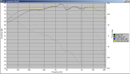
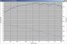
Attached is the result of playing with the crossover sim to try and get something a bit better. Basically I re-did the 1K notch filter I had earlier been using, though I used a different optimisation method and got a somewhat better (simulated) result.
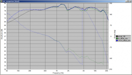
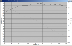
The second plot is the comparison of the actual measured response with the simulation (using individual driver responses taken at the same position) of the current crossover implementation. The blue curve is the actual measured response and black is the sim...
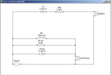
The current crossover schematic is next... as you can see it is rather minimal I had to up the tweeter pad from the actual of 2.2 to 2.6 to get it to correlate properly, I guess that could be the resistance of the wire leading to it, I didn't use particularly heavy gauge wire...
Probably the flattest implementation of the crossover so far is the one in post 75 of the thread linked above. Note that the tweeter network was basically as it is now, the diagram shows what I was planning... note I actually tried that rlc network (but not the resonant peak filter) and got rid of it I ended up also getting rid of the 1K notch because it seemed to be causing distortion... perhaps the 100uF bipolar electro was the culprit there... but as you can see that lead to the most unsatisfactory hump between 1 and 2Khz.
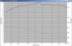
edit: I added a fourth plot, it shows blue, the current actual FR compared to the sim in the first plot...
Tony.
I've thought about having a play with one of the linux based room eq programs before, and I have a linux partition on my pc, so I can do it without disrupting anything . So I might go down that route for a purely testing option (though it would be a listening only test as I would be without my measurement pc)... The thread for my MTM speakers is here http://www.diyaudio.com/forums/multi-way/68301-my-morel-mtm-projects-long-first-post.html Unfortunately like a lot of what I post, it is very verbose! Posts 6 and 7 have the original baffle step sim compared to the measurement I made at the time... Note that the chamfers didn't make much difference at all, and under some circumstances actually make things worse! post 68 has a better comparison of the simmed baffle step compared to the real response the dip is MUCH worse than the sim would imply.
The dip at 2k unfortunately seems to be exacerbated by a natural dip in the woofers response which combines with the effects of my baffle geometry to make a deep well...
Attached is the result of playing with the crossover sim to try and get something a bit better. Basically I re-did the 1K notch filter I had earlier been using, though I used a different optimisation method and got a somewhat better (simulated) result.
The second plot is the comparison of the actual measured response with the simulation (using individual driver responses taken at the same position) of the current crossover implementation. The blue curve is the actual measured response and black is the sim...
The current crossover schematic is next... as you can see it is rather minimal
I had to up the tweeter pad from the actual of 2.2 to 2.6 to get it to correlate properly, I guess that could be the resistance of the wire leading to it, I didn't use particularly heavy gauge wire... Probably the flattest implementation of the crossover so far is the one in post 75 of the thread linked above. Note that the tweeter network was basically as it is now, the diagram shows what I was planning... note I actually tried that rlc network (but not the resonant peak filter) and got rid of it
I ended up also getting rid of the 1K notch because it seemed to be causing distortion... perhaps the 100uF bipolar electro was the culprit there... but as you can see that lead to the most unsatisfactory hump between 1 and 2Khz. edit: I added a fourth plot, it shows blue, the current actual FR compared to the sim in the first plot...
Tony.
Attachments
Last edited:
I want to make a point that I never see come up. I have mentioned it in the past but it never seems to sink in. When we make an on axis measurement we can find the approximate AC by perfroming a HTB on the amplitude data and removing excess phase from the measured phase until the HBT phase matches the measured phase - excess phase.
I explain how to do this here:
Techtalk Speaker Building, Audio, Video, and Electronics Customer Discussion Forum From Parts-Express.com - View Single Post - Unibox to PCD
You know this, but thought I'd post it as it might be useful for others.
Dave
Hi Tony,
20Log(0.2820*SQRT of Sd) Sd is in square metres. Do this for the driver and the port. Just multiply port Sd by 2 for two ports. The answers are in relative dB. Then subtract the port answer from the driver answer and you have the difference that you need totake into account whenyou sum the two together.
Terry
Found a handy tool for the formula.Here it is.
Thanks for thatFound a handy tool for the formula.Here it is.
Although the formula is fairly simple to use manually it's always nice to have a tool like this to remove the possibility of manual calculation errors.
Thanks aucosticraft this is my third attempt at posting, I keep losing what I typed I get some discrepancies when using piston diameter as compared to published effective cone area for my woofer. However I don't have the published piston diameter.
I suspect that you can't just use A = piR^2 to convert the Sd back to a radius and multiply by two.. I get .7db difference if I do that... makes sense I guess as the cone is a cone not a flat circle... It does give me a pretty close result though if I use a ruler and do the measurement including 1/2 of the surround (as is the customary diy measurement for piston diameter)
Tony.
this is my third attempt at posting, I keep losing what I typed I get some discrepancies when using piston diameter as compared to published effective cone area for my woofer. However I don't have the published piston diameter. I suspect that you can't just use A = piR^2 to convert the Sd back to a radius and multiply by two.. I get .7db difference if I do that... makes sense I guess as the cone is a cone not a flat circle... It does give me a pretty close result though if I use a ruler and do the measurement including 1/2 of the surround (as is the customary diy measurement for piston diameter)
Tony.
- Status
- This old topic is closed. If you want to reopen this topic, contact a moderator using the "Report Post" button.
- Home
- Loudspeakers
- Multi-Way
- splicing nearfield to farfield, does this look right?