60dB/oct in a passive filter is impressive! What is the amplitude and phase response like near the cutoff frequency?
A higher data rate may make the DAC more sensitive to internal jitter, but it does not necessarily make it more sensitive to input jitter as internal re-clocking is always possible.
OS digital filtering may need longer data words within the filters, but it does not need longer words at the input. After all, 16-bit data is 16-bit data whatever we do with it.
In the early days of CD the 4xOS with 14-bit DAC used by Philips was generally reckoned to sound better than the NOS 16-bit Sony machines. Were we all mistaken?
Binary 128 x 1,3 = ?
If it was easy to build a perfect os filter, all of them would sound the same, but they don't.
The early Sony players used hybrid filters with bad opamps and bad caps.
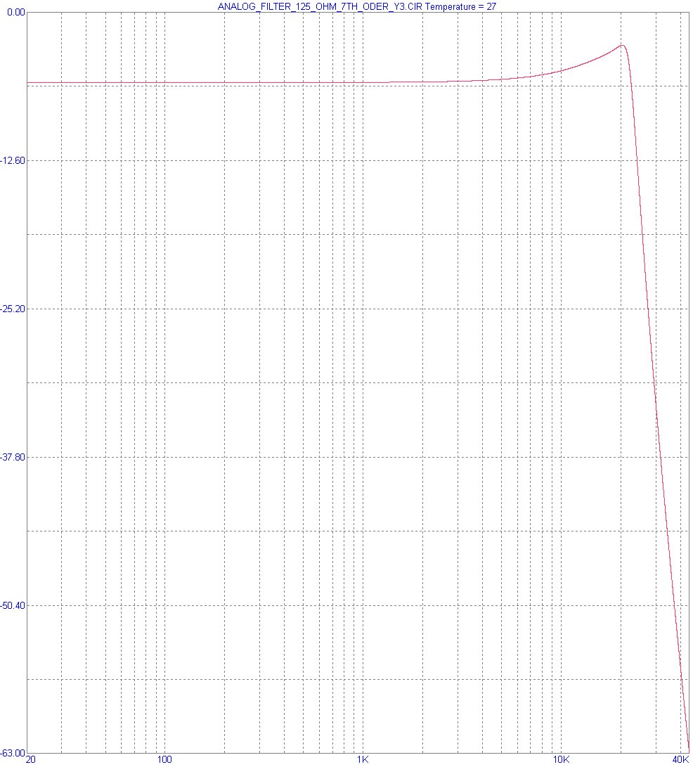
Analog filter:
Phase is -360° @ 20 kHz, makes 1,7cm
Phase is -0,27° @ 20 Hz, makes 1,3cm
Phaseshift over the whole freqency range 20 Hz to 20 kHz is 4mm if my calculations are right.
If you believe this is something to worry about...
I would not even care if it was -800° because 16bit nos with passive brickwall sounds much better than 20bit with a PMD100.
Amplitude:
Last edited:
If it was easy to build a perfect os filter, all of them would sound the same, but they don't.
I'm curious here - how do you know that OS filters don't sound the same? Have you an evaluation jig where all that changes is the filter and nothing else? If so, do please share it here, I'd like to see it.
My guess is you don't have such a thing, and so you're changing more than one variable when you listen between different filters.
It is fairly easy to build an arbitrarily good os filter, its just not doable at a very cheap price as the off-the-shelf filters do have various drawbacks. In the main they're half-band designs so have significant aliasing.
I would not even care if it was -800° because 16bit nos with passive brickwall sounds much better than 20bit with a PMD100.
That's really a passive filter? Do tell us more - it must have plenty of inductors in it, I'd like to learn about those. Are they ferrite cored or air-cored?
I'm curious here - how do you know that OS filters don't sound the same? Have you an evaluation jig where all that changes is the filter and nothing else? If so, do please share it here, I'd like to see it.
When I started testing DAC chips for low level distortion, different os filters showed a different spectrum with the same DAC chip.
Distortion is quiet high, so opamps do not contribute here.
Also those players sounded different.
It is fairly easy to build an arbitrarily good os filter, its just not doable at a very cheap price as the off-the-shelf filters do have various drawbacks. In the main they're half-band designs so have significant aliasing.
Ok, where is the perfect os filter ?
That's really a passive filter? Do tell us more - it must have plenty of inductors in it, I'd like to learn about those. Are they ferrite cored or air-cored?
4 air core inductors.
When I started testing DAC chips for low level distortion, different os filters showed a different spectrum with the same DAC chip.
This sounds interesting - please share some of your findings. Which filter chips and which DAC chip? If filter chips are causing measurable low-level distortion that's really something we should know about. It probably means they're not doing dithering correctly.
Ok, where is the perfect os filter ?
Only in my mind at present
 You'll have to get to build it yourself. Either use a DSP or an FPGA depending on whether you prefer writing software or inputting hardware schematics.
4 air core inductors.
What are their values?
I think your knowledge of physics might benefit from updating. Try reading up on elliptic filters - they achieve cut off slopes better than 6dB per order. Not saying that this filter is for certain an elliptic variant, just there's no law of physics that says filters must obey the rule of 6dB/8ve for each order. Stop band zeros are the key.
4 inductors will make a 24dB per octave, unless the laws of physics are suppressed. That is far from a "brickwall" filter... Actually that is closer of what a OS DAC requires.
How to get 24dB from 4 inductors ?
The values will add up and give 6dB

I didn't see one done with passive components only.
Here's a higher-order example from EDN magazine.
And sure, if you can live with ripple in the whole band, that is great!
Stopband ripple as well as passband ripple, and a truly horrendous group delay towards the corner frequency to boot.
Attachments

This sounds interesting - please share some of your findings. Which filter chips and which DAC chip? If filter chips are causing measurable low-level distortion that's really something we should know about. It probably means they're not doing dithering correctly.
I don't remember, that was years ago.
But one earlier example is TDA1541A with SAA7220A/B.
Only in my mind at present
No thanks.
What are their values?
The filter works only with specified impedances, specified sort and number of DAC chips, no plug & play.
Using it another way would require redesign.
Also posting it here would have various unwanted effects like for example:
Great! Wonderfull elliptic filters... I didn't see one done with passive components only.
And sure, if you can live with ripple in the whole band, that is great!
Here's a higher-order example from EDN magazine.
Stopband ripple as well as passband ripple, and a truly horrendous group delay towards the corner frequency to boot.
Beautiful 5 digit part values
Must see a simulation of that one.
I don't remember, that was years ago.
But one earlier example is TDA1541A with SAA7220A/B.
From memory, the SAA7220 had truly bad stop band rejection and hence serious aliasing at 20kHz. I seem to recall when playing a 20kHz digitally generated sinewave, the distortion was around 1% or so. That wasn't harmonic distortion it was the first image frequency at 24.1kHz.
The filter works only with specified impedances, specified sort and number of DAC chips, no plug & play.
You might take a look at that filter schematic I just posted up. The values for inductors go up into the hundreds of uH. Air-cored, they'd be serious beasts (physically large) and badly prone to noise pickup.
Sorry I forgot to put in the quote from Ken that I was responding to
"1. mainstream (consumer mass market) audio companies don't include a serious listening evaluation as part of the product design process.
2. To include what would necessarily be an iterative subjective listening evaluation as part of the design process would be costly for products with small profit margins and short life spans.
3. The academic based attitude that, if it measures good then, by definition, it sounds good too."
__________________
Here's a higher-order example from EDN magazine.
Stopband ripple as well as passband ripple, and a truly horrendous group delay towards the corner frequency to boot.
Unusable, -3dB point @ 15 kHz
Ken I?
He's a photo-model with his shiny purple shirt
It would be hard to believe they dont have a seriouis listen to their own products ..... Ken Ishiwata not listening ???? no....
He's a photo-model with his shiny purple shirt
Last edited:
Unusable, -3dB point @ 15 kHz
Yes, its a design for an FM multiplex filter, not a CD output filter. I just used it as an example for Sonic to see a passive elliptic filter. If you want to move the corner frequency to 20kHz, that's not hard to do. It hasn't got the stop band rejection that an audiophile reconstruction filter would want though. Suggest if you're serious about wanting to get into designing elliptic filters (or any filters really) you get a copy of Arthur Williams:
Electronic Filter Design Handbook, Fourth Edition McGraw-Hill Handbooks: Amazon.co.uk: Arthur Williams, Fred J. Taylor: Books
- Status
- This old topic is closed. If you want to reopen this topic, contact a moderator using the "Report Post" button.