Hi Brian,
Thanks for the measurements. I feel that they do not simulate what is happening in the initial sections of the SS15 or the fury horn. The aspect ratio of the duct, and the direction of rotation is quite different. I agree, that going by anthing you can find in standard acoustics theory these small reflectors should not be doing anything in the operating frequency range of your tapped horn, they are just too small in comparison to the wavelength involved. As to other restrictions: I'm always surprised how small you can make the Ap1 (throat chamber port area) in Hornresp without markedly reducing the SPL response, I wonder if that holds true at high volumes, or if the losses grow to be too big?
Hi jbell,
Thanks for clarifying your views on the 1/4 wave resonators, I agree. It is also important to remember, that their Q can be tuned, e.g.: with light polyfiber stuffing.
I finally got the clarinet reference. That's a neat thought model.
Regards,
Thanks for the kind words oliver... Occasionally I get the chance to put some of my college education to work. Over the past many months as I've been working through this on what happens why... some of my instrumentation, theory and history classes pop into my head. A study in the differences between a flute (open ended) and clarinet (quasi close ended) was something I remembered. Back when I originally built the 2x2x4 cabinet, I was expecting a huge notch at 1/2wave 140, not 70... looking back at the posts -- I was surprised that I had a non expected huge notch at 70. And listening to my 1hz increment sine waves showed me clearly what was happening. It was like sitting 2 subs side by side and reversing polarity on one of them. After going through the struggles with scott on the fury horn made me immediately try the shallow reflector at the bottom rear of the cabinet. That immediately cured the 70hz, but above that was still troubling. Adding a steeper reflector at the top back of the cabinet cured that, so that I could at least get 40-95hz... wow, all that work for not even an octave and a half... man was that cabinet a disaster. It also occurred to me that long segments close to the throat (higher pressure) are more problematic in band (closer to the clarinet model) than those close to the mouth.(low pressure) The 2x2x4 cabinet was a perfect storm in my mind of bad design -- many dimensions multiples of each other, long passage close to throat, few segments to break up any 'issues.'
I'm the first to admit failure or being wrong. I am very willing to roast hot dogs over the carcass of the failures. However, when I'm on to something.... I stick with it. My current recipe for success in folding a TH is:
No, or very few parallel walls.
tight or 180 bends up front, not at the end, 90's or less only for the last bends.
No two segments the same length
No two overall cabinet dimensions the same or multiples of each other
2 expansion rates, with a break at the expansion change a 'blunt, no reflector 180 degree'
When I follow these rules, I don't need reflectors, they do nothing but subtract spl -- when I break them and have issues -- reflectors (or whatever you want to call them) have saved my butt and salvaged cabinets.
Also, at the frequency where the difference in path length between the inside of the bend and the outside of the bend is N 1/2 wavelengths, there are deep notches in the response. This is a result of the opposite phases recombining (and canceling out) after the bend. A good rule of thumb is make sharp bends with a short radius -or- bend angle is inversely proportional to radius). The point is again remember the "acoustic size" of what ever your dealing with.
I put this to the test tonight, working out what frequency wavelength corresponded to twice that of the difference between the inner and outer paths in my POC #2, which has very similar folding to the THAM15. The lowest it could be is approx 270 Hz (it's likely to be a bit higher), and I'm not seeing any significant deviations in the measured FR at or near that frequency that can't be explained by other means. In any case, it's way outside this horn's passband.
The THAM15 is a larger horn, so that frequency is likely to be a bit lower due to the larger path length difference. Are any measured FR curves for the THAM15 available? It would be interesting to see if there are any significant deviations in the 200 Hz to 300 Hz area, compared to the sim.
Jbell, I'm still reading....................
Brian there is one from Cowan's site:http://cowanaudio.com/images/Andershorn.gif
Brian there is one from Cowan's site:http://cowanaudio.com/images/Andershorn.gif
And I’m totally amazed…
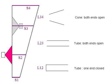
“Open tube: Now a suction at the end of the tube draws air from further up the tube, and that in turn draws air from further up the tube and so on. So the result is that a pulse of high pressure air travelling down the tube is reflected as a pulse of low pressure air travelling up the tube. We say that the pressure wave has been reflected at the open end, with a change in phase of 180°. In the open-open pipe, there is such a reflection at both ends.”
“Now let's look at reflections in a cylindrical pipe closed at one end (such as a clarinet or pipe used as a didjeridu). The reflection at the closed end is easy: the high pressure pulse pushes against the closed end, which pushes back (Newton's third law) and it bounces off the closed wall. A high pressure pulse is reflected as a high pressure pulse, with a phase change of zero in pressure.”
"the pressure node is a little distance outside the pipe, and so L, the effective length of the tube that should be used in such calculations, is a little longer than the physical length of the tube. The end effect is about 0.6 times the radius at an open end."
Last edited:
First off, you got my post all wrong it seems.The 1/4 wave resonators... they work at the FUNDAMENTAL and ODD ORDER harmonics.... Closed ended resonators DO NOT DO ANYTHING AT THE 2nd ORDER HARMONIC... (like your example.) If you want to filter out the odd order harmonics of your horn... you by necessity MUST filter out some of the fundamental. If you design your resonators to hit a specific harmonic as it's fundamental...then what? what is an odd order harmonic of an odd order harmonic? (answer, nothing you care about.) you'd need a wind chime set of resonators to do any good. It makes MUCH more sense (and is 'obviously' what tom did) to tune the resonator to an IN BAND frequency, and then intentionally design a large response spike. The spike and the resonator will counteract each other, and what's left???? the ability for that resonator to filter odd order harmonics. By necessity, when you design a TH with 2 large peaks, there will be a large trough between them, that a series inductor will help with. THAT's the explanation of the dts-20 in my mind.
-The TH is a 1/4WL enclosure. Yes, we all agree.
-The Pipe resonator works on a 1/4WL principles.
-THs as 1/4WL enclosures only have odd ordered harmonics.
-TH have FR Peaks that are determined by these odd ordered harmonics.
-A TH will act on the harmonics regardless of the signal input.
-As a horn gets smaller these FR Peaks will increase in intensity.
The normal way to "fix" them is to use EQ. When EQ is used you limit the amplitude of the incoming signal at the same frequencies these Peaks occur. It does not alter the functioning of these harmonics, as the are still at work in the horn. This is all well and good, until your driver begins to create it's own harmonic distortions.
Let's say the TH has a natural 7th harmonic peak at 80Hz. You EQ, and run a FR sweep to find all is well, so you begin to play sine waves at high power levels, and the driver begins to distort. You get to a long passage with 50Hz waves followed by 40Hz waves. You can tell the 50Hz passage is distorted, but it is bearable. When the 40Hz passage plays you find it is extremely distorted. Why is that?
In this example the driver is distorting the 40Hz wave. It is not contained in the input signal, so the EQ you added is doing nothing for it. Why is it so much worse than the 50Hz wave distortion though you ask? That is because as you play the distorted 40Hz wave a majority of it in this example in 2nd order distortion. That means it is a 80Hz. As your EQ can't do anything about content the driver itself caused the horn goes on about its merry way, and boosts the drivers 2nd order distortion.
To get around this you either find a new horn design, or add a resonator. The resonator can take care of both your problems without EQ, and may not require a whole new horn. You just put a hollow cavity into the high pressure end of the horn to counter the null. The resonator will need to be a 1/4WL in length of the target Peak harmonic frequency, and Q can be adjusted with it's diameter. The resonators will have a couple marks against them.
-They take up horn volume
-They have to be pretty long to get into a subs passband.
As for the clarinet bit, misunderstandings happen; see above.
And I’m totally amazed…
“Open tube: Now a suction at the end of the tube draws air from further up the tube, and that in turn draws air from further up the tube and so on. So the result is that a pulse of high pressure air travelling down the tube is reflected as a pulse of low pressure air travelling up the tube. We say that the pressure wave has been reflected at the open end, with a change in phase of 180°. In the open-open pipe, there is such a reflection at both ends.”
“Now let's look at reflections in a cylindrical pipe closed at one end (such as a clarinet or pipe used as a didjeridu). The reflection at the closed end is easy: the high pressure pulse pushes against the closed end, which pushes back (Newton's third law) and it bounces off the closed wall. A high pressure pulse is reflected as a high pressure pulse, with a phase change of zero in pressure.”
"the pressure node is a little distance outside the pipe, and so L, the effective length of the tube that should be used in such calculations, is a little longer than the physical length of the tube. The end effect is about 0.6 times the radius at an open end."
ahhh.... someone is finding out that clarinets vs flutes is more interesting than trumpets vs trombones....
") It's a great acoustic study.
It's a great acoustic study.martinsson: more area under the curve = good. thanks for sharing.
Last edited:
I'm in a bit of a time squeeze here, but here's a photo of one of the messurements, the MKII in blue :

Br // martinsson
What technique are you using to obtain those measurement results? e.g. is that a close-miked FR measurement?
Remember that the MKII is fitted with B&C 15PS76 unless they took the time to change for an exact comparison.
The 15PS76 is simulated to show more output at 50-60Hz and a slightly less of a dip at 130-220Hz.
btw the original THAM might have a tiny leak due to the slight dip at 16Hz or so. Or it might as well be a measurement artifact.
And as the cab is the same(almost), an increase in SPL is followed by an increase in excursion.
Also followed by a decrease in impedance.
The MKII is said to have subjectively more "kick" from fast kickdrum tracks.
The FR graph does a good job explaining why right?
If you look at the blog it appears to be mic in mouth approach.
If you look at the blog it appears to be mic in mouth approach.
Is that a valid method for doing FR measurements for a system with such a large radiating area?
.Is that a real question, Brian, or is it a valid method for doing forum measurements to find out how large the radiating area is?
That my friend is what is locally known as "jooking ting"
.Seriously, I believe I read something a long time ago that suggested trying to use the close-mike method for measuring a bass-horn's FR was likely to produce a skewed result due to the size of the mouth. OTOH, a tapped horn has a mouth that's a lot smaller than a proper horn with the same F3, so maybe it doesn't apply...
I'm in a bit of a time squeeze here, but here's a photo of one of the messurements, the MKII in blue :
Br // martinsson
I've got a possible "fix" for the THAM15 notch. Well, my rough tests to attempt to fix a similar "problem" with my POC#1 shows some promise.
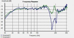
Here's a before/after FR graph from 30 Hz to 300 Hz - before in blue, after in green. Looks like a rough stab at the fix fills in a good portion of the notch, at the expense of a dB or so @ the low end of the passband (which you can likely get back by decreasing S1).
With some fine-tuning, it should be possible to smooth out the FR at the upper end of the passband, particularly considering the crude method I used to alter the FR that way.
The fix (1) doesn't require any major changes to the box dimensions, (2) doesn't involve any sort of "horn voodoo" that's not backed up by known theory, and (3) can quite likely be modelled by Akabak, but probably not HornResp (not enough "taps" along the line's path to model the effect).
For the moment, I'll call it the "Brian Steele's Dog Food" method. Just wish Akabak had a nifty realtime modelling wizard like HornResp to make the iteration process a bit easier.
Interested?
Attachments
Well, even this Horn Voodoo priest is interested in findings from an alien world of scientists!BTW have you checked Martin’s (Xoc1) work from post # 101 (page 11)? He seems to have done some work on that field already.
Yup, saw that. My technique might work a bit better. His mod made a difference of 5dB in the notch, but still leaves a huge hole. If my technique works with the THAM15, it might produce a significantly greater response difference in that area.
Brian, I know you love theories (even if it sounds voodoo at first) just try to get what Jbell is communicating with us...
If you use the rules of harmonics in tubes, both ends open and see L23 that way and suddenly all dips in HornResp show up at predictable points, time after time (lucky guesses right) The only thing I haven't figured out why some are peaks instead of dips... But I'm pretty sure you could help me out with that, well if you are interested of course....
If you use the rules of harmonics in tubes, both ends open and see L23 that way and suddenly all dips in HornResp show up at predictable points, time after time (lucky guesses right) The only thing I haven't figured out why some are peaks instead of dips... But I'm pretty sure you could help me out with that, well if you are interested of course....
Brian, I know you love theories (even if it sounds voodoo at first) just try to get what Jbell is communicating with us...
If you use the rules of harmonics in tubes, both ends open and see L23 that way and suddenly all dips in HornResp show up at predictable points, time after time (lucky guesses right) The only thing I haven't figured out why some are peaks instead of dips... But I'm pretty sure you could help me out with that, well if you are interested of course....
Phase differences along the horn, that's all. JBell's explanation seems reasonable. However, the question to be answered is how can changes to the bends affect the overall response, when these changes are many times smaller than the "acoustic dimensions" required to affect the wavelengths being considered. My own experiments suggest that they don't, so if there is an observable and measurable change, it may be due to something else.
- Home
- Loudspeakers
- Subwoofers
- THAM15 - a compact 15" tapped horn