Folks,
I'm very intrigued by Jack Elliano's 300B design. It's one of those "five parts in a box" kinds of amplifiers. I find the simplicity utterly cool. I do, however, not like that I need 5~6 expensive, heavy, bulky magnetic components to build it, though. I also don't like the use of a 50 W rheostat/variable resistor.
So I was thinking... How about adjusting the bias by adjusting the cathode voltage of the input tube. I came up with attached. I'm curious what you think of it. My main concern is that tube-to-tube variation and drift/aging of the input tube will make the bias of the 300B difficult to adjust and cause it to drift rather quickly. I prefer a "set and forget" kind of design. How valid is this concern?
Thanks,
~Tom
Attachments
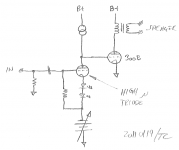
You don't need the B+ on the first stage, simply ground the top of the CCS and use a negative supply below the Cathode LED's. Depending on the driver conditions, a small resistance may be needed in series with the CCS to get the proper bias for the 300B.
With this setup the CCS / resistor setup will assure that the bias voltage remains constant so the current in the output tube will be determined by combination of B+ and individual tube characteristics.
dave
With this setup the CCS / resistor setup will assure that the bias voltage remains constant so the current in the output tube will be determined by combination of B+ and individual tube characteristics.
dave
Dave,
That's a pretty good idea. The only draw-back is that it won't be possible to drive the 300B into A2 with the "top" of the CCS grounded. That might be alright, though...
~Tom
Should be fine as the 300B wasn't really designed for A2 operation, and some of the more cost effective ones can seriously misbehave when driven too hard. (Ask me how I know)

Kevin,
Yeah... I have noticed that the THD goes up beyond tolerable when the tube draws grid current. It's not a desirable operating point for sure. I'm happy as there's no farting out (blocking distortion).
Do you have any concerns with letting the CCS/input tube combo set the bias for the 300B?
~Tom
Yeah... I have noticed that the THD goes up beyond tolerable when the tube draws grid current. It's not a desirable operating point for sure. I'm happy as there's no farting out (blocking distortion).
Do you have any concerns with letting the CCS/input tube combo set the bias for the 300B?
~Tom
Kevin,
Yeah... I have noticed that the THD goes up beyond tolerable when the tube draws grid current. It's not a desirable operating point for sure. I'm happy as there's no farting out (blocking distortion).
Do you have any concerns with letting the CCS/input tube combo set the bias for the 300B?
~Tom
I think the idea has considerable merit, my only concern is with what happens as the driver tube ages and the transconductance falls with the potential drop in effective bias at the grid of the 300B. The only thing I would probably do is meter the "cathode" current in the 300B which is a nice bit of additional bling on the chassis. (Can't hurt, and there are tons of inexpensive Chinese made meters for this purpose on eBay.) The other possibility would be to use a CCS on the plate supply to the output stage with a nice big cap to ground to define the source impedance, while the CCS sets the DC operating point and plate current can never run away regardless of what the driver tube is doing. (I'm experimenting with the same idea in the driver stage of my GM70 - no idea how it sounds yet, but it works great on paper.)
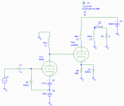
More 300B musings... I'm liking this circuit (attached). It doesn't get rid of the magnetics, though. Tradeoffs, tradeoffs...
In the sim, I end up with roughly 420 V across the 300B and an idle current of 100 mA. The 5842 tube runs at 11 mA.
~Tom
In the sim, I end up with roughly 420 V across the 300B and an idle current of 100 mA. The 5842 tube runs at 11 mA.
~Tom
Attachments
Last edited:
This was done originally by Oldeurope (former member) for a 300b. Once you dial in the parts values, it's very stable - essentially self settling. Two tubes and a few resistors and caps (which can all be film - even the power supply).
http://www.diyaudio.com/forums/attachment.php?postid=1690207&stamp=1229725484
Sheldon
http://www.diyaudio.com/forums/attachment.php?postid=1690207&stamp=1229725484
Sheldon
More 300B musings... I'm liking this circuit (attached).
In the sim, I end up with roughly 420 V across the 300B and an idle current of 100 mA. The 5842 tube runs at 11 mA.
~Tom
Hi Tom,
The dcr of that choke is going to have to be at least 7 - 8K to develop the required bias and I would worry (as I do) about the tempco of that resistance. (Although it will drift in the safe direction.) The other concern is the 5842 itself, operating points all over the map from sample to sample with fixed bias due to the very high slope of the transconductance I do use the 5842 choke loaded with 1.8V led bias on a 100V supply to drive 71A in my headphone amp, but I selected tubes that met the design criteria, and its AC coupled..
One other thing is that pd is rated at 40W for a generic 300B and other than the JJ I have not had good luck with affordable types running at over 70mA.. I run my JJ at 400V/80mA and they have run about 5000hrs so far with no sign of failure. Some types will not run safely at 400V at any current. (Older Shuguang, Valve Arts, etc.)
Last edited:
The other possibility would be to use a CCS on the plate supply to the output stage with a nice big cap to ground to define the source impedance, while the CCS sets the DC operating point and plate current can never run away regardless of what the driver tube is doing.
One suggestion: Try running the cap to the B+ supply rather than to ground. It'll keep the top end of the OPT primary referred to B+ rather that GND. I can't decide if that's an improvement or not, but it's definitely something I'd try. It may improve the supply sensitivity.
~Tom
One suggestion: Try running the cap to the B+ supply rather than to ground. It'll keep the top end of the OPT primary referred to B+ rather that GND. I can't decide if that's an improvement or not, but it's definitely something I'd try. It may improve the supply sensitivity.
~Tom
Actually the reverse I think, the point being to isolate the load and driver stage entirely from the supply, and from an AC standpoint the supply would have to provide that AC ground reference anyway with some potential penalty due to the quality of the supply caps, etc.. Just one cap sets the LF pole and there is no source of ripple injection into the driver circuitry which allows the use of a very poorly regulated and filtered supply. The AC loop is also entirely contained within the first stage and AC signal current does not flow through the supply at all.
One other thing is that pd is rated at 40W for a generic 300B and other than the JJ I have not had good luck with affordable types running at over 70mA.. I run my JJ at 400V/80mA and they have run about 5000hrs so far with no sign of failure. Some types will not run safely at 400V at any current. (Older Shuguang, Valve Arts, etc.)
I intend to run the 300B fairly hot. In my current design I run about 365 V, 95 mA. It's been running for weeks without issues, but obviously that doesn't say much about long-term reliability. I wouldn't mind getting a bit higher voltage (maybe 400-ish) and 90-ish mA. But I'll try your 400V/80mA as well.
~Tom
Actually the reverse I think, the point being to isolate the load and driver stage entirely from the supply, and from an AC standpoint the supply would have to provide that AC ground reference anyway with some potential penalty due to the quality of the supply caps, etc.. Just one cap sets the LF pole and there is no source of ripple injection into the driver circuitry which allows the use of a very poorly regulated and filtered supply. The AC loop is also entirely contained within the first stage and AC signal current does not flow through the supply at all.
Good point. I'll buy that.
As far as I can tell, the cap to ground will then "see" the output impedance of the CCS in parallel with the primary impedance in series with rp of the output tube (Z = Zcss||(Zprimary+rp)). So you should even be able to get away with a fairly small cap and still have a, say, 1 Hz -3 dB point. /me like...
~Tom
Folks,
I'm very intrigued by Jack Elliano's 300B design. It's one of those "five parts in a box" kinds of amplifiers. I find the simplicity utterly cool. I do, however, not like that I need 5~6 expensive, heavy, bulky magnetic components to build it, though. I also don't like the use of a 50 W rheostat/variable resistor.
Thanks,
~Tom
Tom, I built a pair of Jack's 300b amplifiers even though I was not fond of all the magentics and the 50W power resistor either. This was my first venture into the building of SE amplifiers even though I have built a lot of push pull amplifiers in my life. I must say, Jack's design has worked well for me and is a good sounding amplifier. I had my own power transformers wound by Edcor and used a pair of Transcendar output transformers I got for Christmas a year ago. I did purchase all the chokes from Jack. I have had fun with this project and had to satisfy my curiousty about SE ended amplifiers. Good luck on your 300b project. Mickeystan
The dcr of that choke is going to have to be at least 7 - 8K to develop the required bias and I would worry (as I do) about the tempco of that resistance.
Hello Kevin,
I am not sure how you mean but suppose your´re thinking of grid bias only? Let´s say we have typical 1k rdc and 5842 11mA. We then get -11V on the 300B grid. The rest of the bias should/could be achieved with cathode-bias as I see it.
Still grounding the top of the choke is a great idea.
Tom hadn't mentioned anything about partial cathode bias and at those plate voltages the typical 300B is going to need -75v to -85V grid bias to achieve a reasonable quiescent operating point. A resistor could be used to make up the difference if necessary - use a pot and resistor and it then becomes comparatively easy to set the output stage quiescent current without changing the operating point of the driver. (I'd place the pot and resistor on the cold side of the choke.)
I use fixed bias in all of my 300B designs and much prefer the performance without a nasty cathode bypass cap in the signal path.
Last edited:
One should absolutely put the resistor on top/cold side. Question is if there should be a capacitor connected to ground from the junction of the resistor and choke.
To keep track of the DC-levels one could also add a Rod Coleman style simple servo. But that might impair sound quality.
To keep track of the DC-levels one could also add a Rod Coleman style simple servo. But that might impair sound quality.
Question is if there should be a capacitor connected to ground from the junction of the resistor and choke.
Did some error-thinking there. No need for a cap.
I would also dump the input cap in favour of a transformer.
Tom, I built a pair of Jack's 300b amplifiers even though I was not fond of all the magentics and the 50W power resistor either. This was my first venture into the building of SE amplifiers even though I have built a lot of push pull amplifiers in my life. I must say, Jack's design has worked well for me and is a good sounding amplifier. I had my own power transformers wound by Edcor and used a pair of Transcendar output transformers I got for Christmas a year ago. I did purchase all the chokes from Jack. I have had fun with this project and had to satisfy my curiousty about SE ended amplifiers. Good luck on your 300b project. Mickeystan
Exactly how does one contact Transcendar for list of offerings, prices, etc?
- Status
- This old topic is closed. If you want to reopen this topic, contact a moderator using the "Report Post" button.
- Home
- Amplifiers
- Tubes / Valves
- DC coupled 300B idea - request for comments