Well, not entirely. Some more careful sims shed a bit more light on the subject.Quite right, my bad.
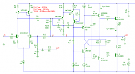
The first pic below shows the circuit used for the tests. R8, R9 and D1 form a non-linear dummy load, roughly representing the input impedance of a double-EF output stage. This dummy load was only included for the distortion tests.
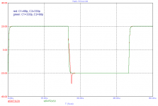
The second pic shows the gain and phase with no load. Swapping the values of C1 and C2 makes a barely noticeable difference, perhaps a quarter dB at most.
The third pic is where it starts getting interesting. This shows the output impedance, measured by injecting a signal into the output of the VAS through a 1 Meg resistor, with the input shorted. Although the difference isn't as big as I originally expected, it shows that swapping the caps does have a significant effect on the output impedance.
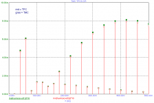
With a non-linear load connected to the output of the VAS, a higher output impedance should result in higher distortion. The forth pic shows that this is indeed the case, with distortion products being about 6 to 10dB higher between 10 and 20KHz, where the output impedance is about 2 to 3 times higher.
So is it worth worrying about?
Probably not, as it only affects distortion caused by non-linearity of output stage current gain. In practice, this is likely to be less significant than other distortion sources.
Even when this is the dominant source of distortion, it would probably still be a good idea to have C1 > C2, although a less extreme ratio would probably be called for. As Edmond pointed out earlier, other problems arise when C2 > C1.
Attachments

Hi Godfrey,
THD20 figures for C1>C2, respectively C1<C2 are not always unambiguous. Depending on circuit details, sometimes I got better results with C1<C2, sometimes just the opposite. But in all cases, the step response is horrible when C1<C2.
See the figures below. In this case C1>C2 is the winner, also THD-wise.
Cheers,
E.
PS: Is anybody interested in a fair apples to apples comparison between TMC and (compensated) TPC?
Attachments
Well, not entirely. Some more careful sims shed a bit more light on the subject.
The first pic below shows the circuit used for the tests. R8, R9 and D1 form a non-linear dummy load, roughly representing the input impedance of a double-EF output stage. This dummy load was only included for the distortion tests.
The second pic shows the gain and phase with no load. Swapping the values of C1 and C2 makes a barely noticeable difference, perhaps a quarter dB at most.
The third pic is where it starts getting interesting. This shows the output impedance, measured by injecting a signal into the output of the VAS through a 1 Meg resistor, with the input shorted. Although the difference isn't as big as I originally expected, it shows that swapping the caps does have a significant effect on the output impedance.
With a non-linear load connected to the output of the VAS, a higher output impedance should result in higher distortion. The forth pic shows that this is indeed the case, with distortion products being about 6 to 10dB higher between 10 and 20KHz, where the output impedance is about 2 to 3 times higher.
So is it worth worrying about?
Probably not, as it only affects distortion caused by non-linearity of output stage current gain. In practice, this is likely to be less significant than other distortion sources.
Even when this is the dominant source of distortion, it would probably still be a good idea to have C1 > C2, although a less extreme ratio would probably be called for. As Edmond pointed out earlier, other problems arise when C2 > C1.
Hi Godfrey,
Nice work, especially the part about VAS output impedance. It is very important for designers to understand what influences the VAS output impedance and the role it plays in keeping distortion down and in keeping open-loop amplifier output impedance low, especially at high frequencies.
We should not underestimate the influence of nonlinear signal current being drawn by the output stage, especially when only a double is being used. This is another reason that I strongly prefer Triples for power amplifiers.
Cheers,
Bob
TMC vs TPC
Hmm...... apparently nobody, not even Bob? In that case I will cease my efforts to shed more light on this topic.
.................
PS: Is anybody interested in a fair apples to apples comparison between TMC and (compensated) TPC?
Hmm...... apparently nobody, not even Bob? In that case I will cease my efforts to shed more light on this topic.
godfrey,
There`s no reason to say sorry. Modified to "The final result is much higher distortion", your statement will be entirely correct.Unfortunately, doing that loads the input of the VAS heavily, reducing its open-loop gain. The final result is likely to be much higher distortion.
godfrey,
Right, having a current gain of one, just as it should be ideally.My concern was to do with the current gain of the VAS. An "ideal" VAS would have a low input impedance, and act as a virtual earth input device.
A totally wrong approach.However, a Blameless-style Darlington VAS has a very high input impedance (and, potentially, a very high current gain).
Voltage operated at all frequencies. (It would be weird otherwise).Perhaps it would be more correct to think of the VAS as a voltage operated device at high frequencies.
Member
Joined 2009
Paid Member
Hmm...... apparently nobody, not even Bob? In that case I will cease my efforts to shed more light on this topic.
It's been an interesting thread, a kind of summary comparison would be useful, even if not entirely objective, such as:
distortion reduction - both pretty much the same ?
amplifier stability - both pretty much the same ?
affect on the sound - both pretty much the same ?
cost of implementation - both pretty much the same ?
I'm not trying to be facetious here, I think it would be good if the 'Experts' could boild down the discussions to something that less expert people could use as a guide.
In my next Lin topology amplifier - how should I implemented a good compensation scheme ?
Last edited:
Edmond:
I am and am sure there are others who are as well.
mlloyd1
I am and am sure there are others who are as well.
mlloyd1
Hi Godfrey,
...
PS: Is anybody interested in a fair apples to apples comparison between TMC and (compensated) TPC?
Hmm...... apparently nobody, not even Bob? In that case I will cease my efforts to shed more light on this topic.
Please do Edmond.
I don't post a lot but I am following along.
David.
It seems that there s some misunderstanding about TPC/TMC
so called equivalence.
As pointed by Edmond, one can t expect much if the two compensation
schemes use the same components , as it become then more of a kind
of optimization under constraints which are no more to optimize for the
amp best possible behaviour, but rather to optimize given a particular
case, ie, the same components for both TPC and TMC..
So far, given the amps resulting cracteristics, and in the limits of
my simulations, TMC provide the better outcome overall , but with
the limitation i already much talked about, ie, the higher IMD ratio
if care is not taken to design accordingly to TMC requirements.
Member
Joined 2009
Paid Member
design accordingly to TMC requirements.
can you summarise what these are ?
can you summarise what these are ?
The requirements have been much publicized by Edmond.
A very high gain VAS.
Some pointed also an adequate input stage
that can supply/sink enough current, although this latter
requirement is easily reached since TMC allow for a slightly
lower Cdom, thus reducing the said need.
Also, and this reflect only my point of view, a high slew rate
VAS , as i suspect that it s the cause of the higher IMD ratio
of TMC in my simulations, rather than the input stage current
capabilty as proposed by some as the explanation.
TMC vs TPC
Hi everyone,
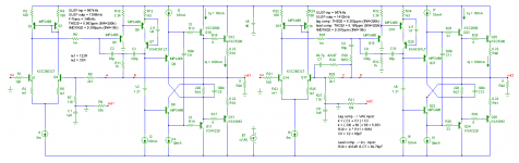
Here follows another attempt to compare both techniques on a level playing field (apples to apples). The objective is the keep all key parameters as much as possible the same: unity loop gain frequency (ULGF) including the IPS as well as the ULGF including the OPS (at node A and C, respectively B and D), the step response and the compensation components. However, as already pointed out and repeated by wahab, you can't get optimal results if one uses exactly the same capacitors in both versions. For TMC Ci must be smaller than Co and for TPC Ci must be larger than Co (which, by the way, still isn't understood by our TPC 'expert'). To circumvent this dilemma, one may simply swab the caps. As the capacitor ratio is 'irrelevant' according to our TPC expert, he surely hasn't any objections to do so. I have tried several ratios between 1:1 and 1:10 and it appeared that 1:5 is near optimal in terms of distortion and stability. So, for the TMC version Ci=68pF & Co=330pF and for the TPC Ci=330pF & Co=68pF.
Another concern is the step response of TPC. It is often suggested to correct it by means of lead compensation in the NFB network(see C7 & R29), However, for a true apples to apples comparison, this method is not correct, as the ULGF, seen at the IPS, is about 40% higher. A better approach is to put a lag compensation between the VAS input and the OPS output (C8 & R30) in order to get the same step response and the same ULGFs compared to TMC. See megajocke's contribution for the analysis and calculation of the component values.
First pic. at the left side: TMC; at the right side TPC
Oops! Pushed the wrong button. I'm not ready yet. I will continue on a next page.
NB: Ci is the comp. cap. at VAS input and Co is the comp. cap. at VAS output.
I wanted to answer, that "we all want to hear about comparisons", but realised I cannot speak for all, so refrained.
It's been an interesting thread, a kind of summary comparison would be useful, even if not entirely objective, such as:
distortion reduction - both pretty much the same ?
amplifier stability - both pretty much the same ?
affect on the sound - both pretty much the same ?
cost of implementation - both pretty much the same ?
................
Edmond:
I am and am sure there are others who are as well.
mlloyd1
Please do Edmond.
I don't post a lot but I am following along.
David.
It seems that there s some misunderstanding about TPC/TMC so called equivalence. As pointed by Edmond, one can t expect much if the two compensation schemes use the same components , as it become then more of a kind of optimization under constraints which are no more to optimize for the amp best possible behaviour, but rather to optimize given a particular case, ie, the same components for both TPC and TMC..
...........
Hi everyone,
Here follows another attempt to compare both techniques on a level playing field (apples to apples). The objective is the keep all key parameters as much as possible the same: unity loop gain frequency (ULGF) including the IPS as well as the ULGF including the OPS (at node A and C, respectively B and D), the step response and the compensation components. However, as already pointed out and repeated by wahab, you can't get optimal results if one uses exactly the same capacitors in both versions. For TMC Ci must be smaller than Co and for TPC Ci must be larger than Co (which, by the way, still isn't understood by our TPC 'expert'). To circumvent this dilemma, one may simply swab the caps. As the capacitor ratio is 'irrelevant' according to our TPC expert, he surely hasn't any objections to do so. I have tried several ratios between 1:1 and 1:10 and it appeared that 1:5 is near optimal in terms of distortion and stability. So, for the TMC version Ci=68pF & Co=330pF and for the TPC Ci=330pF & Co=68pF.
Another concern is the step response of TPC. It is often suggested to correct it by means of lead compensation in the NFB network(see C7 & R29), However, for a true apples to apples comparison, this method is not correct, as the ULGF, seen at the IPS, is about 40% higher. A better approach is to put a lag compensation between the VAS input and the OPS output (C8 & R30) in order to get the same step response and the same ULGFs compared to TMC. See megajocke's contribution for the analysis and calculation of the component values.
First pic. at the left side: TMC; at the right side TPC
Oops! Pushed the wrong button. I'm not ready yet. I will continue on a next page.
NB: Ci is the comp. cap. at VAS input and Co is the comp. cap. at VAS output.
Attachments
Last edited:
TMC vs TPC
Continued from post 3334
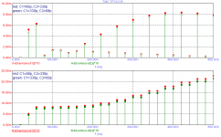
Harmonic distortion at 20kHz (BW=200k)
TMC: 8.563ppm
TPC: 8.362ppm
So TPC is slightly better, 2.4%. But why? Let's have a look at the individual distortions of each stage (IPS, VAS and OPS), by replacing subsequently two stages by ideal components (VCCS, CCCS and VCVS).
(BTW, I've also simmed the TPC version with lead compensation and other capacitor ratios, but I got almost the same THD20 figures, except for the IPS distortion)
Distortion of the IPS
TMC: 0.551 ppm
TPC: 0.569 ppm
As can be seen, almost the same.
For completeness, in case of TPC with lead compensation instead of lag compensation, the distortion is much lower: 0.029 ppm, most likely due to a lighter load of the IPS. However, on the overall distortion this has little effect (8.195 vs 8.362 ppm), as both figures are relative small wrt the total distortion.
Distortion of the VAS
TMC: 0.022 ppm
TPC: 0.101 ppm
Clearly, TMC performs much better. Who says that the VAS doesn't benefit from TMC?
Distortion of the OPS
TMC: 7.894 ppm
TPC: 7.993 ppm
As expected, TMC and TPC do equally well.
From above individual figures, one might conclude that the total distortion of TPC should be slightly higher than TMC. However, as it appeared, this is not the case, probably due to some cancellation, respectively augmentation effect. Or could it be explained by differences in ULFG? Probably not, as the differences are too small:
TMC: ULGF-inp = 997kHz ULGF-outp = 1398kHz
TPC: ULGF-inp = 957kHz ULGF-outp = 1412kHz
And finally the IMD figures derived from 19 and 20kHz (BW=18kHz)
TMC: 0.398 ppm
TPC: 0.387 ppm
Also in this case TMC performs slightly better, though again a minuscule 2.8%.
Bottom line: Applied to typical power amplifiers, TMC and TPC do equally well, though TMC requires less components.
Cheers,
E.
Continued from post 3334
Harmonic distortion at 20kHz (BW=200k)
TMC: 8.563ppm
TPC: 8.362ppm
So TPC is slightly better, 2.4%. But why? Let's have a look at the individual distortions of each stage (IPS, VAS and OPS), by replacing subsequently two stages by ideal components (VCCS, CCCS and VCVS).
(BTW, I've also simmed the TPC version with lead compensation and other capacitor ratios, but I got almost the same THD20 figures, except for the IPS distortion)
Distortion of the IPS
TMC: 0.551 ppm
TPC: 0.569 ppm
As can be seen, almost the same.
For completeness, in case of TPC with lead compensation instead of lag compensation, the distortion is much lower: 0.029 ppm, most likely due to a lighter load of the IPS. However, on the overall distortion this has little effect (8.195 vs 8.362 ppm), as both figures are relative small wrt the total distortion.
Distortion of the VAS
TMC: 0.022 ppm
TPC: 0.101 ppm
Clearly, TMC performs much better. Who says that the VAS doesn't benefit from TMC?
Distortion of the OPS
TMC: 7.894 ppm
TPC: 7.993 ppm
As expected, TMC and TPC do equally well.
From above individual figures, one might conclude that the total distortion of TPC should be slightly higher than TMC. However, as it appeared, this is not the case, probably due to some cancellation, respectively augmentation effect. Or could it be explained by differences in ULFG? Probably not, as the differences are too small:
TMC: ULGF-inp = 997kHz ULGF-outp = 1398kHz
TPC: ULGF-inp = 957kHz ULGF-outp = 1412kHz
And finally the IMD figures derived from 19 and 20kHz (BW=18kHz)
TMC: 0.398 ppm
TPC: 0.387 ppm
Also in this case TMC performs slightly better, though again a minuscule 2.8%.
Bottom line: Applied to typical power amplifiers, TMC and TPC do equally well, though TMC requires less components.
Cheers,
E.
Member
Joined 2009
Paid Member
does that equate to TMC being easier to set up a stable amplifier for the less skilled constructors?Applied to typical power amplifiers, TMC and TPC do equally well, though TMC requires less components.
TMC vs TPC
Continued from post 3336
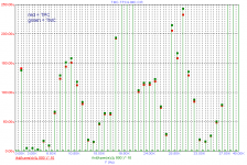
Here are a few more pics:
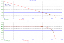
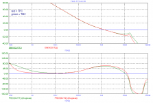
Global loop response, IPS included.
Global loop response, OPS included,
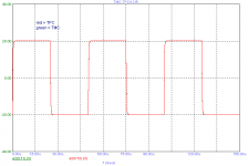
Step response.
TMC curves (green) are hardly visible, because they coincidence with the TPC curves (or apples to apples).
Cheers,
E.
Continued from post 3336
Here are a few more pics:
Global loop response, IPS included.
Global loop response, OPS included,
Step response.
TMC curves (green) are hardly visible, because they coincidence with the TPC curves (or apples to apples).
Cheers,
E.
Attachments
- Home
- Amplifiers
- Solid State
- Bob Cordell Interview: Negative Feedback